Exercise 4
Allow at least 30 minutes to reconstruct assets; further time will be needed for texturing or other details to be added.
Part B: Building a prehistoric house in Blender 2.9.3.1
A step-by-step video for Exercise 4B can be found here.
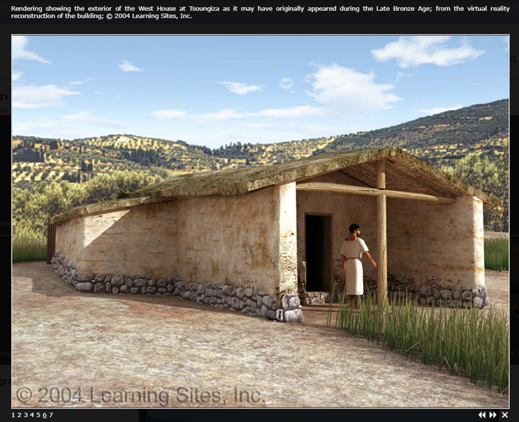
While greyboxing may give us enough to work with to meet the some of the most basic requirements of our reconstruction (layout of buildings/walls and scale of features), it is likely that you will want to model assets to provide a more detailed interpretation of the site. For this, we may want to review some reference images for proposed reconstructions of Middle/Late Bronze Age structures in Greece (have a look online, but be critical; which seem credible?). For the purposes of this exercise, we will go through how to recreate the basic form of one of the Late Bronze Age houses at Tsoungiza.
Though there are many Blender tutorials available online that walk you through creating architectural assets like houses, our process will be more complicated, as we are working with the reality-captured data as a footprint for the shapes we’ll be creating. The structures at Malthi were not as rectangular and regular as a modern house.
Do note that there are many different ways to approach 3D modelling, and the below is just one possible workflow. It could be that you may want to block out each potential structure first, leaving roofs and other structural details until the last step. However, this tutorial is designed to familiarise you with the basic 3D modelling tools and features so that you can develop your own preferred workflow.
Think and Respond: Consider the area of the site that you have already greyboxed; how many of these walls do you think could have feasibly belonged to a single, roofed structure? How many basic shapes will you need to put together to recreate the visible footprint of the structures?
Modelling
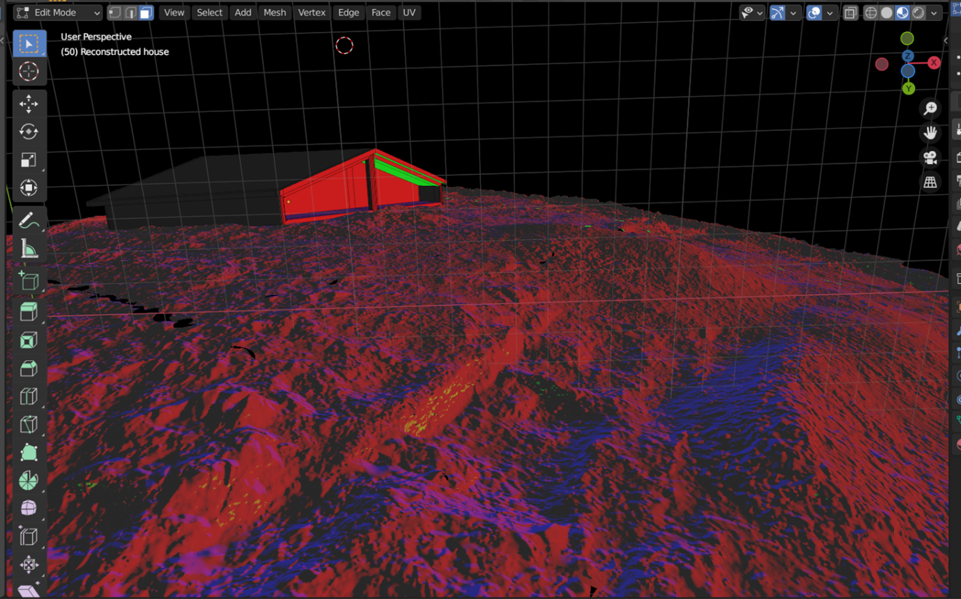
Because we want to build off of our meshed laser scan data of the site, it is useful to have the ‘Snap’ function enabled to snap to ‘Vertex’, functions you can find across the top of your ‘3D Viewport’ in its toolbar – this way you can ensure that your modelled assets will be sitting directly on the stone foundations. This exercise will be focusing on the footprint of a potential building in the northern region of the upper terrace.

First, let’s build our structure from a basic cube.
-
While in ‘Object’ mode, hold down ‘Shift + A’ keys and navigate to ‘Mesh’ and then ‘Cube’. A new 3D cube will appear wherever your ‘3D Cursor’ is located.
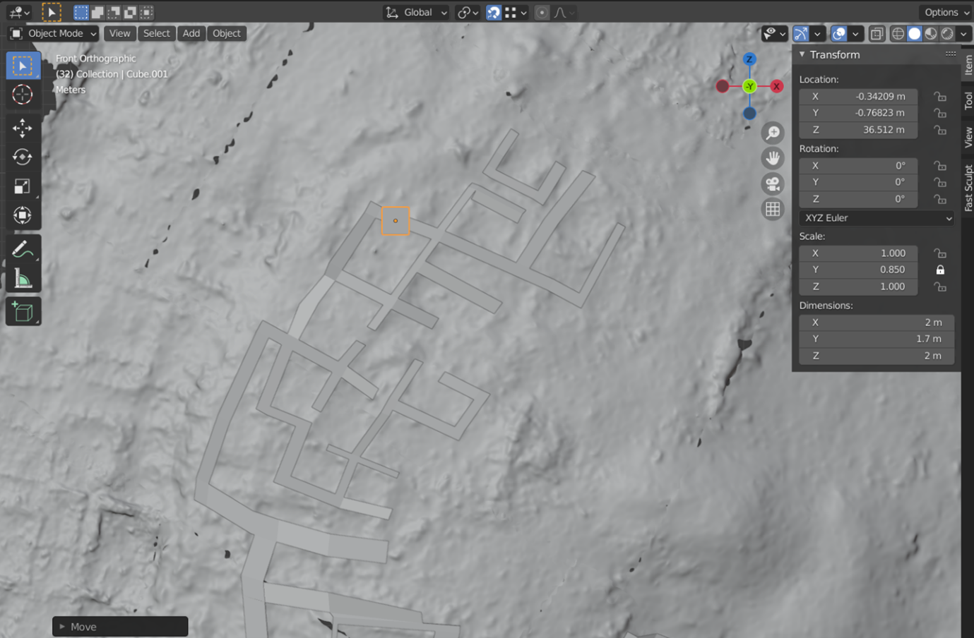
- We’ll first need to decide what dimensions will need to stay static – as we heard from Dr Worsham in Exercise 2, it is thought that the height of a single storey building would likely be at least 1.5 metres high. This should be roughly consistent across the site, though recall Dr Worsham thought that the buildings surrounding or on the upper terrace could have been two storeys tall. To ensure that our building stays the same size when we scale the width and length of the building, press the ‘N’ key to bring up the ‘Transform’ panel.
- In the Transform panel, change the ‘Dimensions’ value next to your height axis (throughout this exercise, the steps will be treating the ‘Y’ axis as height) to your chosen height for a single storey (in this case, 1.7 m; or double the value for a two-storey building!) and lock the ‘Scale’ for this same axis.
- Now we need to align our ‘building’ to its ‘footprint’ on the site. Ensure that your cube is highlighted in the ‘Scene Collection’ area before switching from Object to ‘Edit mode’. Press ‘2’ to ‘Select Edges’. Left-click on the first corner you want to reposition so that it is highlighted, then press the ‘G’ key – the corner of the cube will now follow your mouse. Because you should still have the ‘Snap to Vertex’ function on, it should be relatively easy to pull the corner of your cube to the desired position. It should snap to the laser scanned data, but you can also use your greyboxed outlines to set the corners of the cube, if they are visible in the space.
- This may take a bit of further consideration as you block out an actual building – decide what ‘unit’ you are working with in this case. Although there may be many internal rooms covered by a single building, how would it have appeared to someone standing outside of the structure? Try to define your single ‘roofed’ unit before progressing. Do you feel a two-storey building would be more accurate than a single-storey building? You need to have decided what ‘unit’ you’re working with here – how would the building have appeared externally, do you think? Try to define a single ‘roofed’ unit before progressing.
As discussed in Exercise 2, we don’t know what the roofs of the structures at Malthi would have looked like; there are many forms they could have taken, and they could have been mudded, thatched or wooden. If we are trying to recreate the roof used in the Tsoungiza example above, we may prefer a slight peak to the roof (for guidance in constructing other types of roofs, see ‘The CG Essentials’ YouTube channel: https://youtu.be/Pcb-BBeGt8w).
Remember to save!
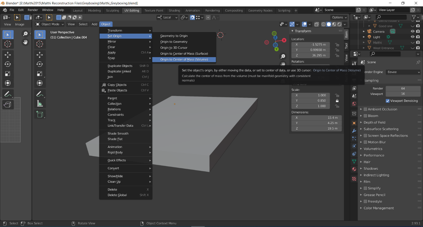
Before we start on the roof, we need to set the ‘centre’ of our object to make local transformations easier. Because we have created an irregular shape for our building to match the reality-captured floorplan, many of the ‘easy’ modelling functions that are used in 3D modelling tutorials may act oddly unless this is set. Switch to ‘Object mode’, and under ‘Object, navigate to ‘Set Origin’, then ‘Origin to Centre of Mass (Volume)’. In the toolbar for your 3D Viewport, switch to ‘Local transformation orientation’.
Now, let’s build our theoretical roof.
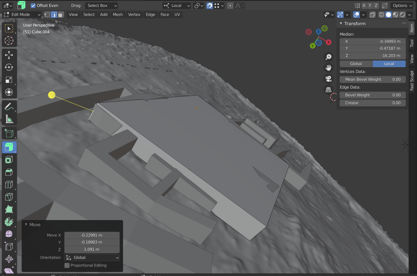
- Switch to ‘Edit mode’; to create a slight, triangular peak to our cube, we will need to add what Blender calls a ‘loop cut’. A loop cut will divide a loop of consecutive faces, based on your placement, to create a series of new edges. Switch to ‘Select faces’ by pressing the ‘3’ key, then press the ‘Ctrl + R’ keys; a glowing yellow line will appear to bisect your cube. Position this so that it cuts across the ‘roof’ of your cube, then left-mouse click when it is positioned correctly. Left-click a second time to finalise its placement.
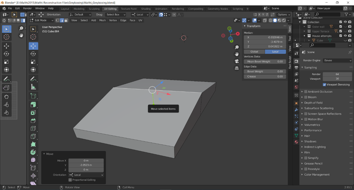
- To create the peak of the roof, switch to ‘Select Edge’ (by pressing the 2 key ), select the edge across your roof, and press ‘G’ to move it upwards; you can either do this freehand/by eye, or you can specify which axis it should follow. Because we created a slightly irregular shape with this cube, it may not be the perfect solution – in the example shown below, I was able to use the ‘Y axis’ to guide the roof to the correct position.
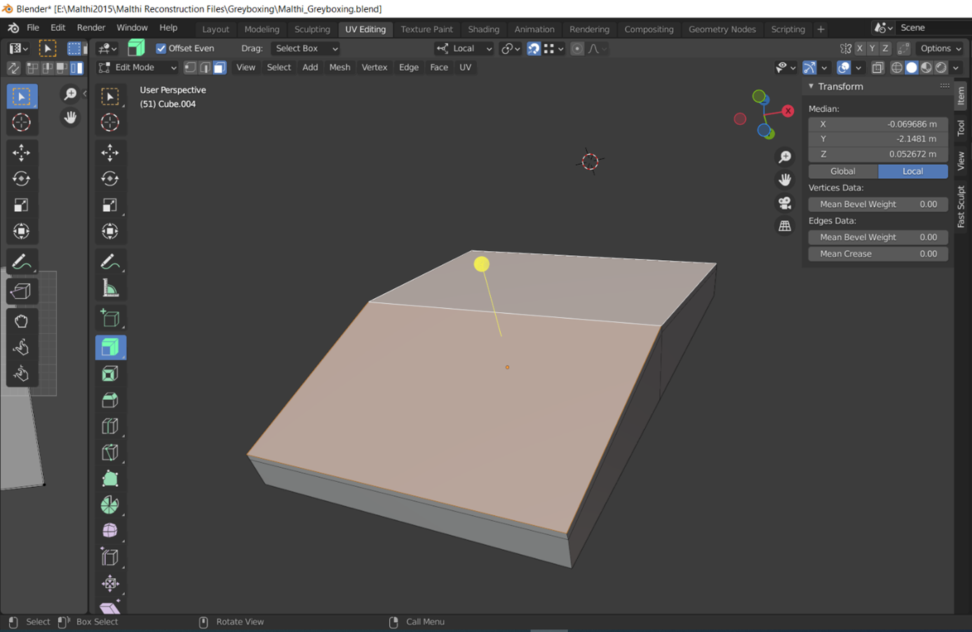
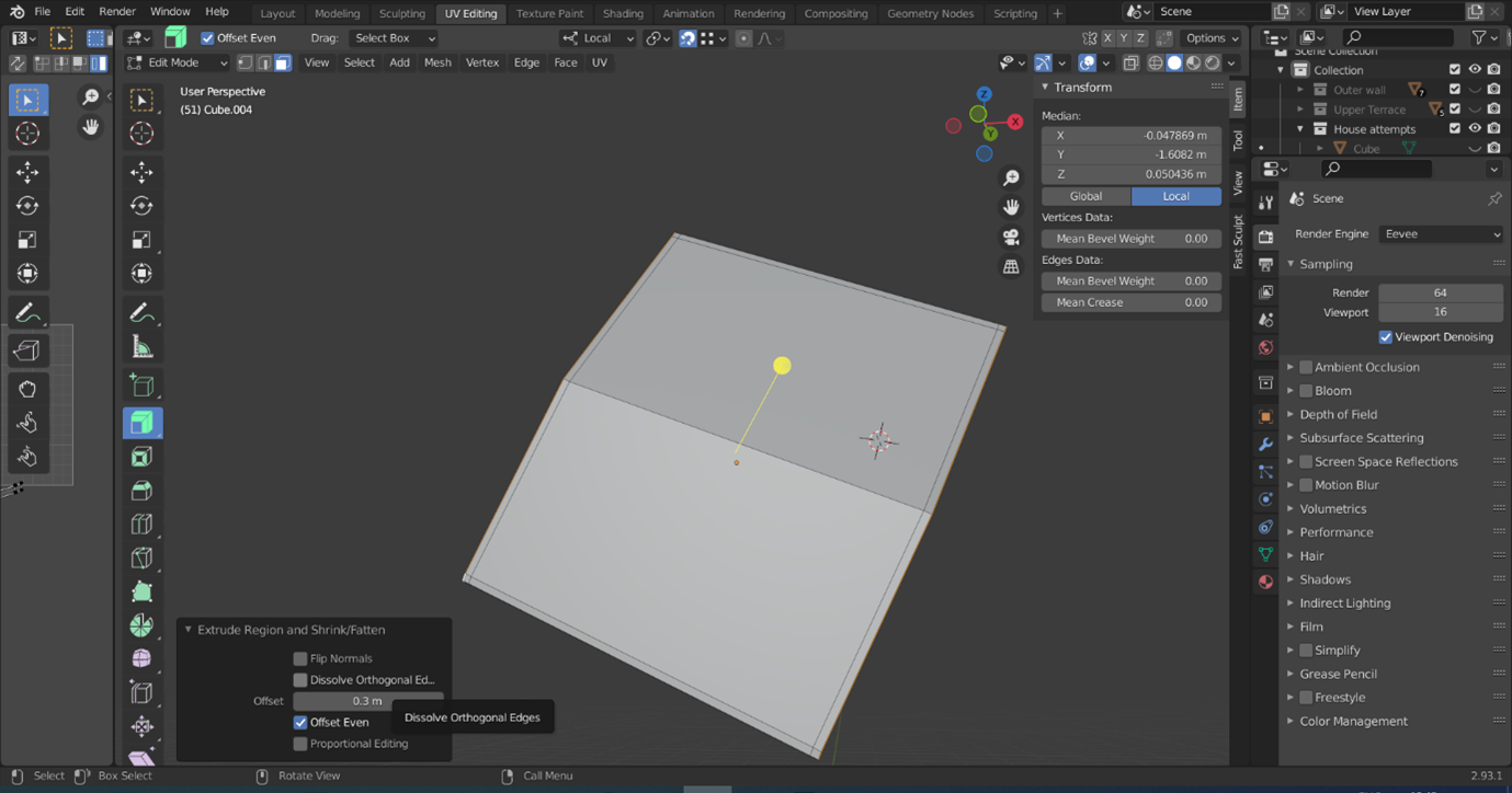
- Once you are happy with the angle of your roof, switch to Select Faces (by pressing the 3 key), select the two faces forming the top of your roof, and ‘extrude along normals’ (the ‘Extrude’ hotkey is ‘E’, tthough you need to make sure that it is extruding ‘along normals’. If you hover over the ‘Extrude’ toolbar on the left side of the 3D viewport [see the tool highlighted in blue below], you ensure the option is selected by clicking and hold the extrude tool in the toolbar to view more options). In the menu that appears at the bottom left corner of the viewport, you can also set the extruded space to a set distance (in this case I have used 0.3 m).
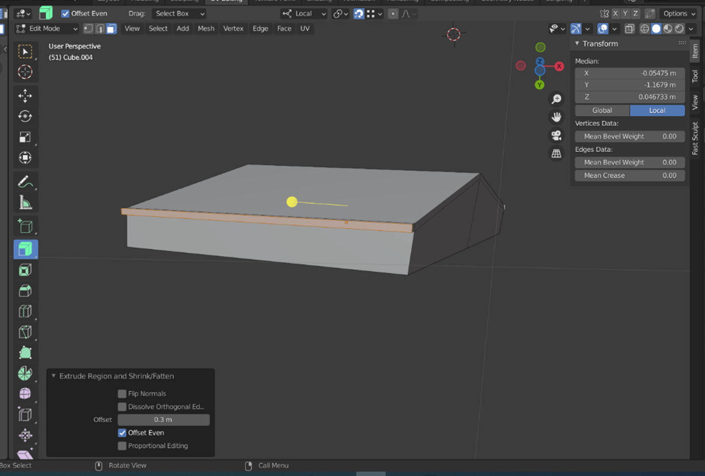
- Next, we may want to extend the roof slightly beyond the wall of the structure. Again, while in ‘Select Faces’ mode, select the faces comprising the sides of your roof (Shift + left click to select multiple faces).
- Click on the ‘Extrude Along Normals’ tool in the side toolbar, then click and drag the yellow ‘plus’ button that appears on screen; you may also want to hold the CTRL button while moving your mouse button, as this should extrude the roof in small increments.
- Next, press the ‘G’ key and move your mouse to align the roof edge into a more realistic position. If you press the ‘Y’ key (or X or Z), this should restrict the movement of the roof edge along your chosen local axis.
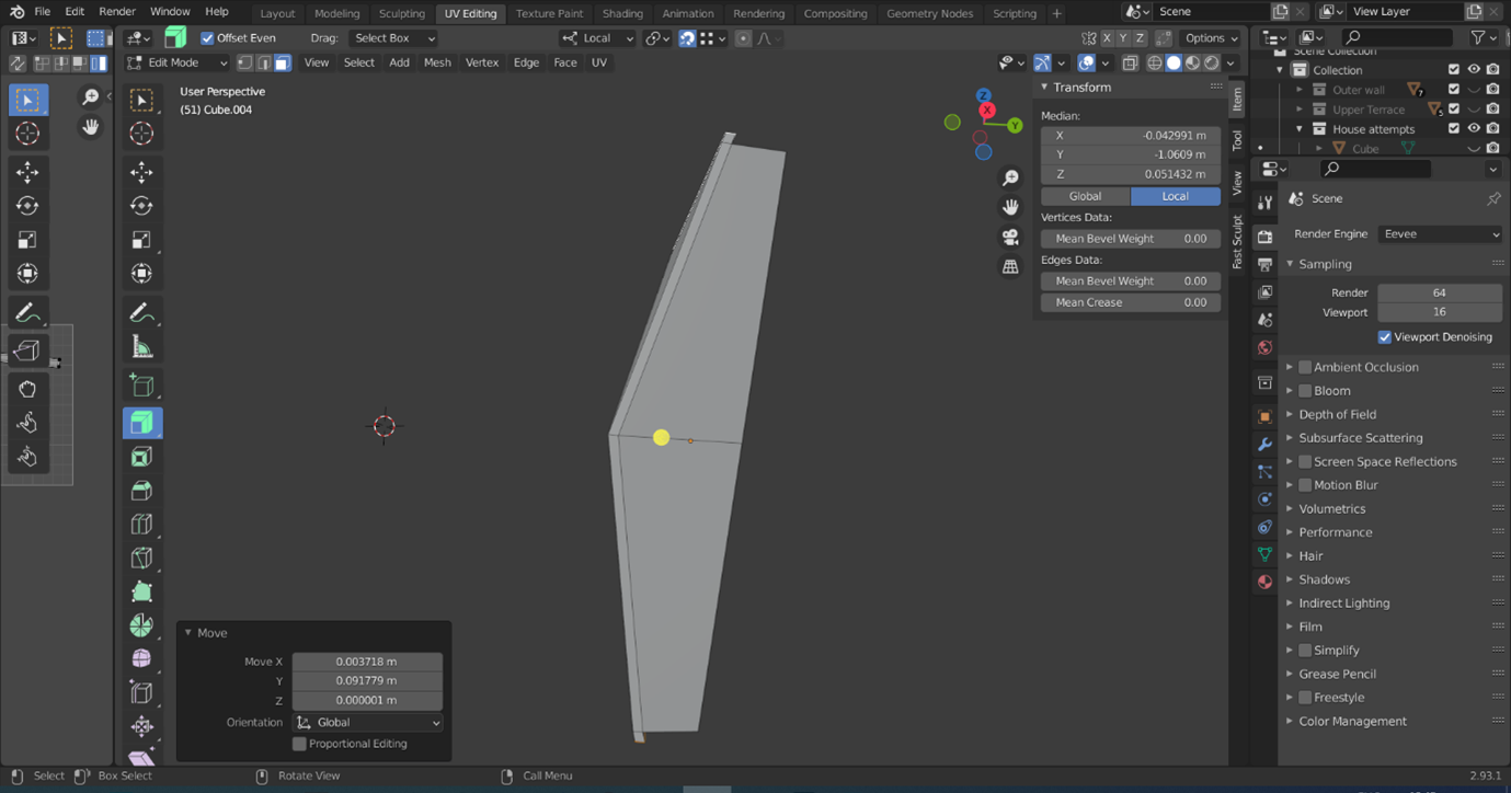
- Select the faces of the front and back edges of the roof ( Shift + left click as before to select multiple faces), and extrude these out as well along their normals, as you did for the side parts of the roof.
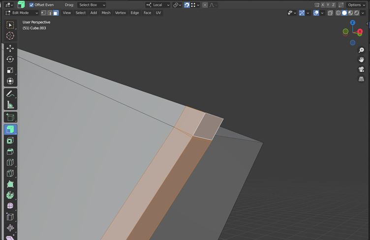
- It’s important to note here that there may be issues with the corners of your roof because we began with an irregular shape. Luckily there is a simple way to fix this; simply switch to ‘Select Faces’ (using the 3 key) and select a few of the faces that need to be joined together.
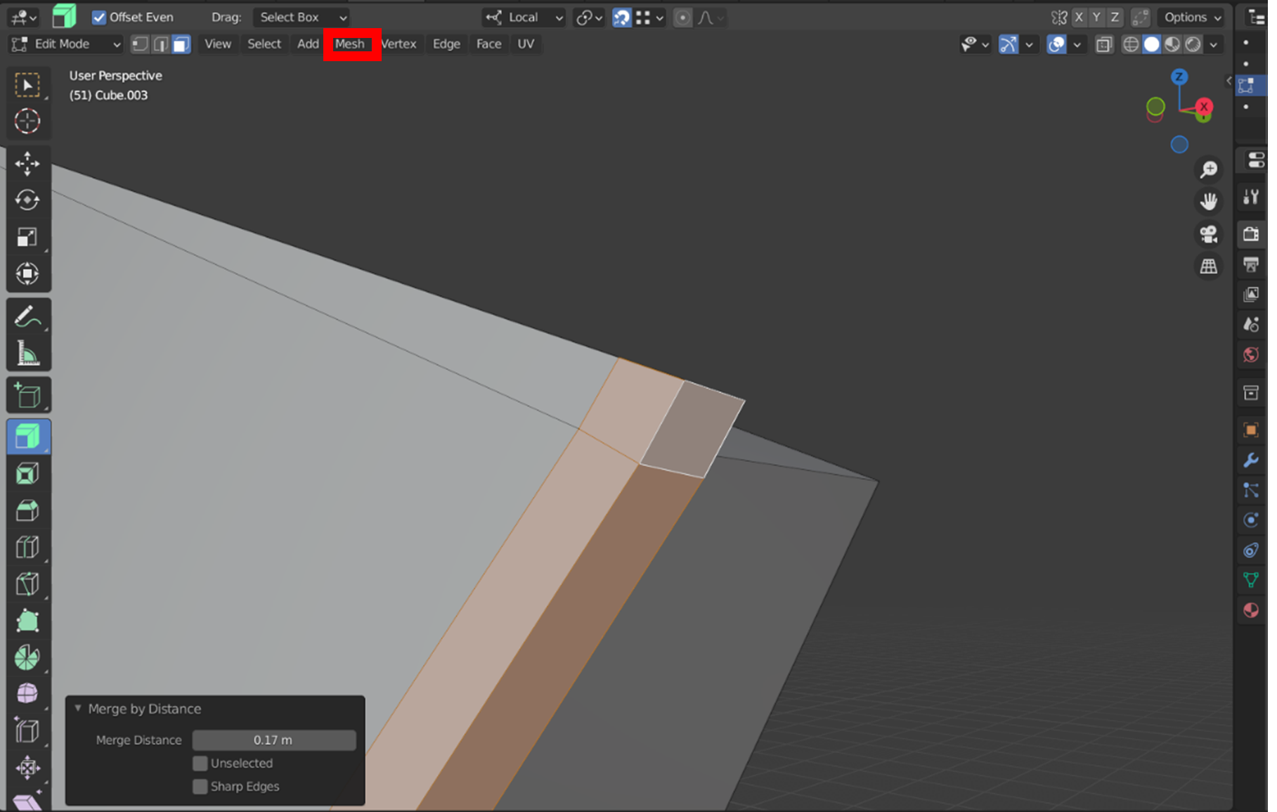
- Then, in the ‘Edit Mode’ toolbar, navigate to the ‘Mesh’ dropdown menu (highlighted with a red box below), ‘Clean Up’, then ‘Merge by Distance’. A new panel will appear in the bottom left corner of the viewfinder – left click and drag the bar to the right next to ‘Merge Distance’ until the overlapping or gapped geometry merges together.
- Remember to Save!
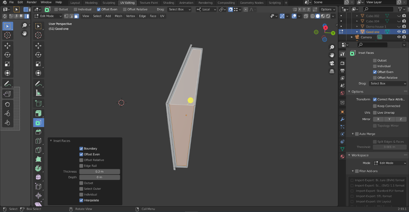
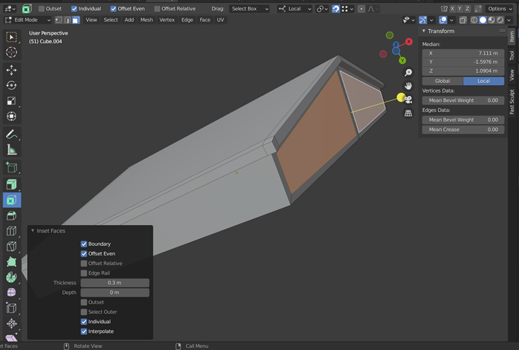
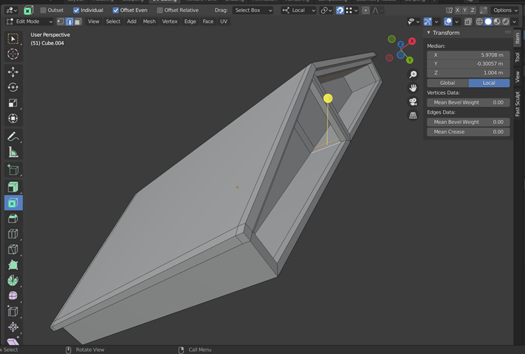
- To create the ‘porch’ area seen in the Tsoungiza reconstruction above, select the two faces comprising the front of your structure. Select ‘Inset Faces’ (shortcut ‘I’ key) with ‘Boundary’, ‘Offset Even’, and the ‘Interpolate’ options selected. Click and drag the ‘Thickness’ scale to 0.3 m or more, as this defines how much space is left at the edge of your structure to form your walls.
-
If you want to create a ‘support pillar’ as pictured in the Tsoungiza reconstruction, ensure that ‘Individual’ is also checked.
-
Select your new inset faces and use the ‘Extrude along normals’ tool to push this surface back into the structure.
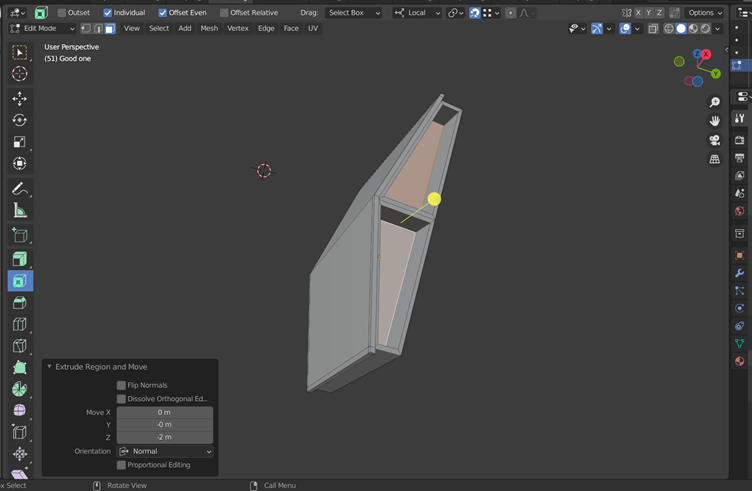
- To make your post look a bit more like a post instead of a dividing wall, use the ‘Loop cut’ function again to outline where your post will be going. Take note of the number used as the ‘Factor’ for the Loop cut function so that you can repeat this on the other side.
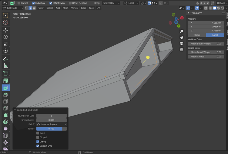
- After creating your loop cuts, switch to ‘Face Select’ (3), and select the face that you wish to delete (see below). Hit the ‘Delete’ key, and select ‘Faces’, or it will delete other parts of the geometry you won’t wish to lose.
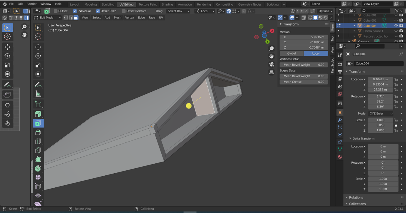
- Once you have deleted both faces, switch to the ‘Edge Select’ tool (2) and select two of the edges of the holes you have made. Use the ‘Fill’ function (F key) to fill these in.
Remember to Save!
Whether you created the post at the front of the structure or not, our house is looking quite angular for a prehistoric building. While the visible foundations of the buildings at Malthi are largely rectangular, they often have rounded corners. To simulate this, we will use the ‘Bevel’ function.
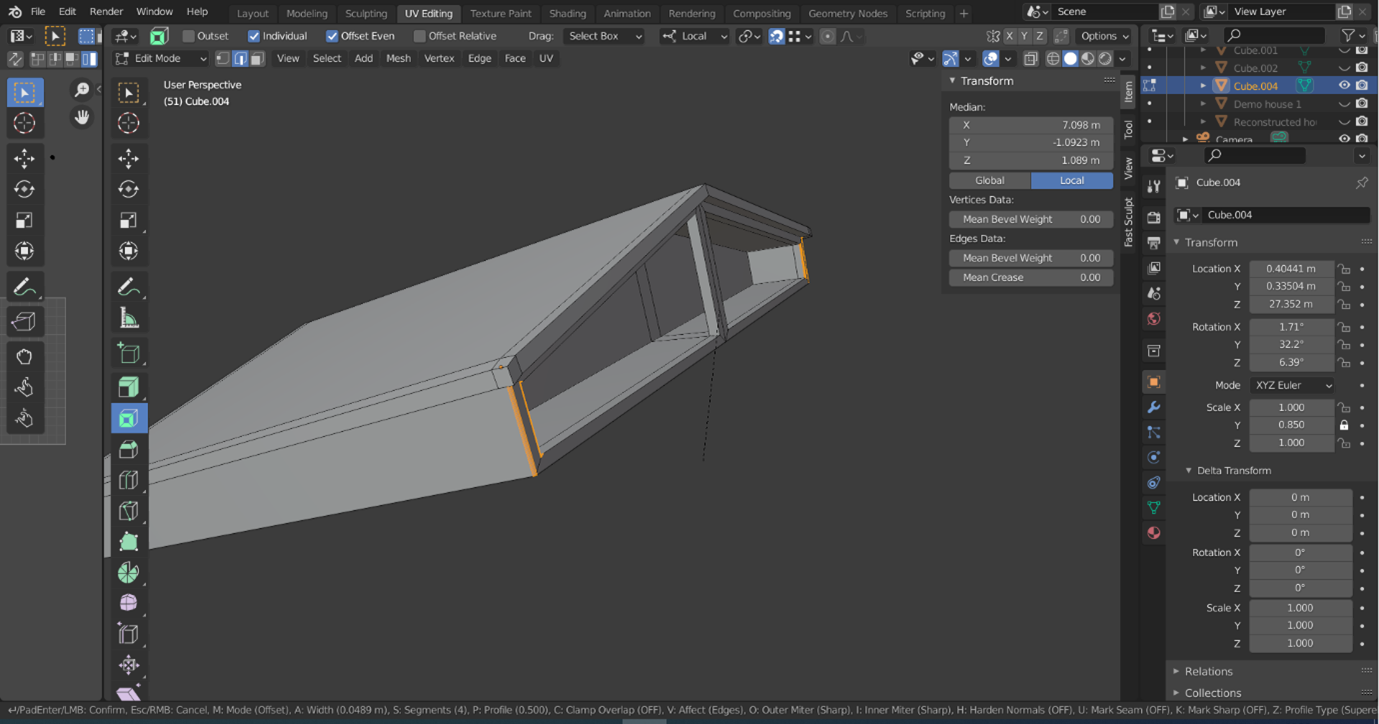
- To use ‘Bevel’, switch to ‘Select Edges’ (2) and select the edges that you want to be treated with a similar level of bevelling. For this exercise, I chose to bevel the four edges forming the two front-facing faces the building at the same time (pictured below). After selecting the edges, use the shortcut Ctrl + B to enable the bevel tool.
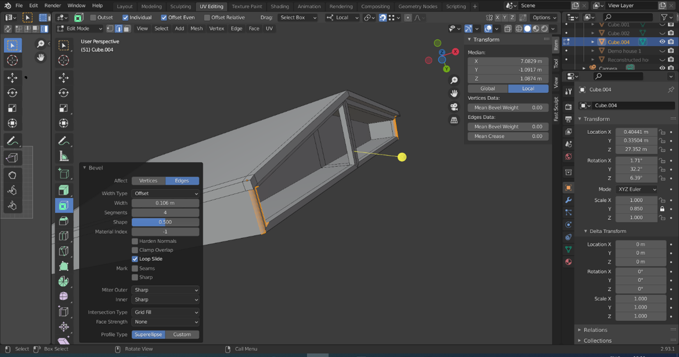
- As you can see in the screenshot above, the bottom edge of the screen will then be filled with information on how to use the tool – most of these settings you will want to leave alone, but as you pull your mouse away from the object, you will notice orange lines appearing (and your geometry likely exploding if you pull it too far away). This is because the distance you pull the mouse away indicates how much of the surface you want to bevel, and the small surface between edges is causing the bevels to overlap.
- Hold the Ctrl key as you pull your mouse away from the object for a more controlled application of bevelling. Roll your mouse wheel to increase the number of ‘segments’ the bevel incorporates – this will create a smoother bevel. Left click once you are happy with the appearance of the bevel and a new information panel will appear, allowing you to alter the bevel further if needed.
- The bevel can also be applied to the back corners of the structure, the edges of the roof, and even the four corners of the ‘support post’.

Try it yourself! If you wanted to add the cross-beam to your modelled house to better replicate the Tsoungiza reconstruction, how would you do this in Blender? At which step would you have added it? Try adding another building – are there any differences in the floorplan of this structure that affected how you designed this second structure?
Think and Respond: After greyboxing Malthi and reconstructing a hypothetical Bronze Age structure to fit the extant structural remnants on site, has this helped you to understand the site better? Is there anything you noticed about the site through the process of modelling? How did the process of modelling affect your interpretation of the site?
Overall, this exercise has introduced you to many of the essential 3D modelling tools in functions in Blender, including:
- How to build on primitive shapes and adapt them to fit reality-captured data;
- the differences between faces, edges, and vertices;
- and how to scale, extrude, move, inset, loop cut, and bevel these geometric features.
If you wish to try applying textures to your house, continue to Part C of Exercise 4 before Exporting.
Export
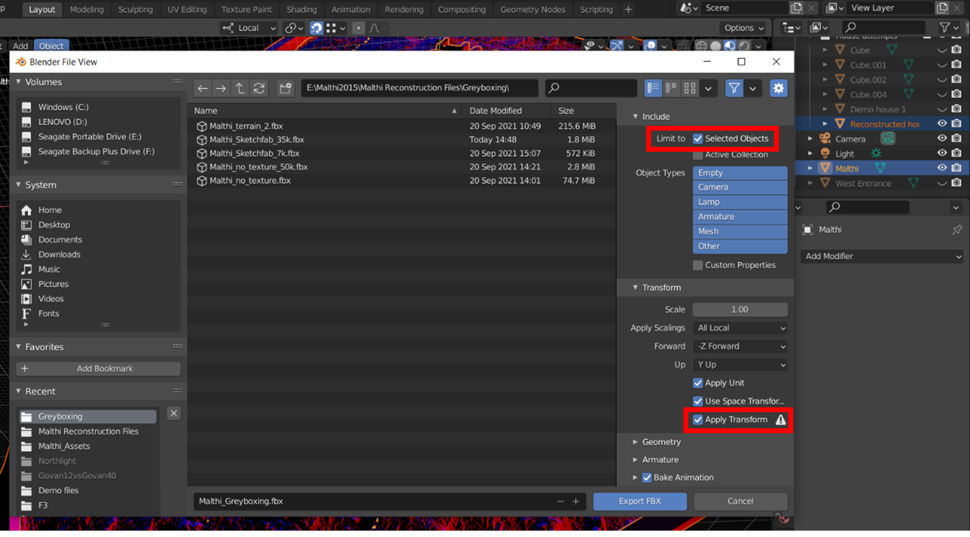
Once you have created your reconstruction, it is time to export your creation for use in another venue (Sketchfab, Unity, Unreal, etc). If we want to maintain the positioning of our different features, we may want to export all of our greyboxed walls, our reconstructed house, and the base-map of Malthi. Ensure that all of these are selected in the ‘Scene Collection’ window by left-clicking them while holding the Ctrl key.
Once these are highlighted, navigate to ‘File > Export > FBX’. This will bring up a window where you have many options. First, name your file a sensible name. Then, ensure that you check the ‘Limit to Selected Objects’ box and the ‘Apply Transform’ options. Then click ‘Export’.
All of the associations with materials will be maintained in this file. You can change the orientation of your reconstruction before exporting, by changing the ‘Forward’ and ‘Up’ settings, but ensure that you know what orientation the destination game engine or 3D hosting platform uses (though in most cases it is quite simple to realign your reconstruction, even if you misjudge it here).
Think and Respond: Do you feel that these assets are sufficient for a reconstruction of the site? What do you feel is missing? While sculpting individual bricks into the side of your reconstructed house might be satisfying, is it necessary to fulfil the brief? Do you need a textured house for the purposes of your reconstruction?
Resources for Exercise 4:
- Kormann, M., Katsarou, S., Katsonopoulou, D. and Lock, G. 2015. Structural Integrity Modelling of an Early Bronze Age Corridor House in Helike of Achaea, NW Peloponnese, Greece, CAA Proceedings- Siena 2015, 825-836. URL: http://www.helikeproject.gr/discoveries.htm
- Worsham, R., Lindblom, M., and Zikidi, C. 2018. Preliminary report of the Malthi Archaeological Project, 2015–2016. Opuscula, 11: 7-28.
- Lile, D. 2020. "Intro to Blender UV Mapping". YouTube. Uploaded by Darrin Lile, 19 May 2020, https://youtu.be/GTd8NBg8EZU
- The CG Essentials. 2020. "How to Model 7 Different Kinds of ROOFS in Blender - Architectural Modeling Tutorial". YouTube. Uploaded by The CG Essentials, 10 August 2020, https://youtu.be/Pcb-BBeGt8w.
- The Institute for the Visualization of History. 2012. http://www.vizin.org/projects/tsoungiza/gallery.html.
| Go back to Part A of Exercise 4 | Go to optional Part C of Exercise 4 | Go to Exercise 5 |