Exercise 4
Allow at least 30 minutes for the greyboxing activity (Exercise 4A). Additional time may be required for greyboxing larger areas of the site.
Part A: How to model assets in Blender
A step-by-step video for Exercise 4A can be found here.
In the first three exercises, you generated clean, georeferenced meshes of the archaeological structures visible at Malthi, considered how best to represent these features, and optimised the dataset to build upon it. In this exercise, we will first discuss the process and benefits of greyboxing, a term that was introduced in Exercise 2. Then, we will go through the basics of modelling assets (using Blender version 2.93.1) and how to apply textures to those assets, should you choose to do so. We’ll then discuss how to export your final reconstructed assets for use in Exercise 5.
For this exercise, you may wish to choose one section of the site to work with (one which you have already prepared through Exercises 1 – 3). If have prepared the data from the entire site, the optimised dataset can still be small enough that you’ll be able to progress through this exercise.
While we could introduce infinite amounts of detail, depending on your level of artistic skill, this exercise will focus on introducing the technical skills necessary to address our primary aims – creating a scaled reconstruction, populated with hypothesized structures that can help us understand how the site would have been navigated during the Middle/Late Bronze Age. As you will see in the next steps, greyboxing and modelling a site have significant archaeological value as a thought experiment and interpretive exercise. These processes can help you try new configurations of features to test whether make sense, given the evidence.
Key Blender Shortcuts
Blender 2.93.1 has many shortcuts that make it easier to work in the software. Listed below are a few that are essential to the exercise below.
Navigation:
Zoom: Scrolling Mouse-wheel
Rotate: Clicking the mouse-wheel and moving your mouse
Pan: Click mouse-wheel and hold the Shift key
Tab: Change between Object mode and Edit mode
1: Select Vertices (use the 1 from the top row of your keyboard, not the numpad)
2: Select Edges (use the 2 from the top row of your keyboard, not the numpad)
3: Select Faces (use the 3 from the top row of your keyboard, not the numpad)
Create:
Shift + A: Add a primitive mesh
Ctrl + R: Loop cut
S: Scale
R: Rotate
E: Extrude
G: Move
Uncreate:
Ctrl + Z: Undo
Delete key: Will delete faces, edges, or vertices you have selected
Note: There are also a number of add-ons created by the Blender community that may make your construction experience easier (like Archipack or Archimesh, which are architecture-focused add-ons) – however, this exercise will focus on introducing the simple tools that are fundamental to modelling anything in Blender.
Greyboxing the site
As explained in Exercise 2, Greyboxing is a technique used in video game design to quickly test how a game level should be laid out. In this case, greyboxing will be a key tool in understanding the walls at Malthi. How do we visually differentiate between walls, tumble, piles of displaced stone from Valmin’s excavation, and exposed bedrock? How do we decide which walls are external and which were internal divisions? If you’re uncertain, you can always have a look at the maps from Worsham et al’s preliminary report on Malthi (2018) to aid in your wall identification. Even once we’ve identified the walls, we need to decide how the structures would have been accessed. Where are the doors? The stairways? This is where you would be discussing these issues with archaeologists familiar with the site to make better informed decisions. But for now, we will see how greyboxing affects our own interpretation.
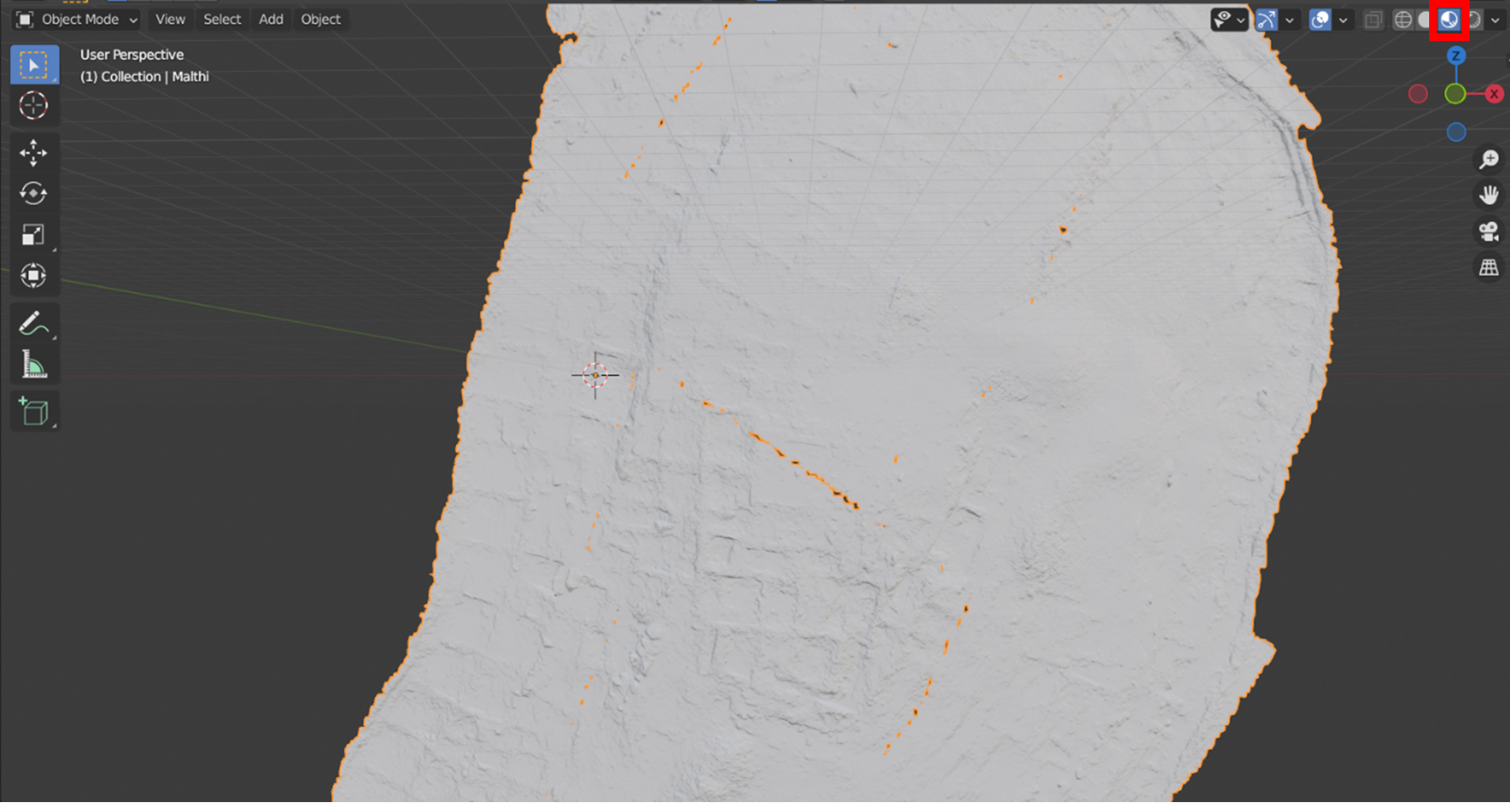
- Begin with one section of the site that particularly interests you and that has been optimised and normal mapped. (The screenshots for this exercise will focus on the structures on the upper terrace.) Import your exported file from Exercise 3 into a new Blender file by navigating to File > Import > and then the file type of your exported data. Once the mesh appears, enable the ‘Viewport Shading’ option in the top right corner to see the normal mapped information on the mesh.
- For this greyboxing exercise, we will be using cube primitives to outline the probable walls of the site. Primitives are pre-made basic 3D shapes included in 3D modelling software and are often used as the building blocks to 3D modelling.
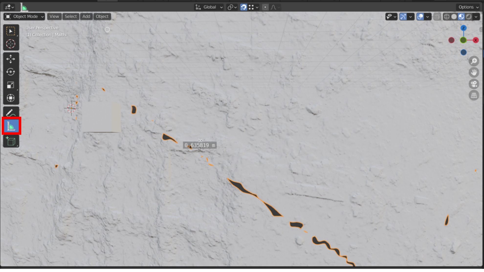
- First, we should decide on a relatively consistent width and height to give our cubes. If we use the ‘Measure’ tool, we can decide what a good width for the internal walls will be, as the length will be variable. Select the measure tool from the left toolbar (highlighted with a red box in the image below). Choose the starting point for your measurement, left click, hold and drag your mouse to the second point , then release. This will provide a scaled measurement for that feature. If we do this for several walls, it appears that most have a thickness between 0.6m and 0.7m. (To remove the measurement annotation, click on the annotation and hit the ‘delete’ key on your keyboard).
-
If we think back to Exercise 2, Dr Worsham had suggested that most one-storey buildings would likely be around 1.5 m tall. We can also scale our primitive cubes to reflect this.
- To create a cube, press the Shift and A keys at the same time to bring up the ‘Add’ menu. From here, navigate to ‘Mesh’ and select ‘Cube’. A new cube will be added to the ‘Scene Collection’ list and will appear on your ‘3D cursor’ (the crosshairs surrounded by the red and white circle in your 3D viewport). You may need to zoom out ( scrolling with your mouse-wheel ) or pan the scene ( clicking the mouse-wheel and holding the shift key ) to find your cube.
- You can press the ‘G’ key to move the cube in 3D space. Turn on the ‘Snap’ function of the 3D viewport space and set it to ‘Vertex’. This will help ensure that our greyboxing ‘sticks’ to the Malthi dataset.

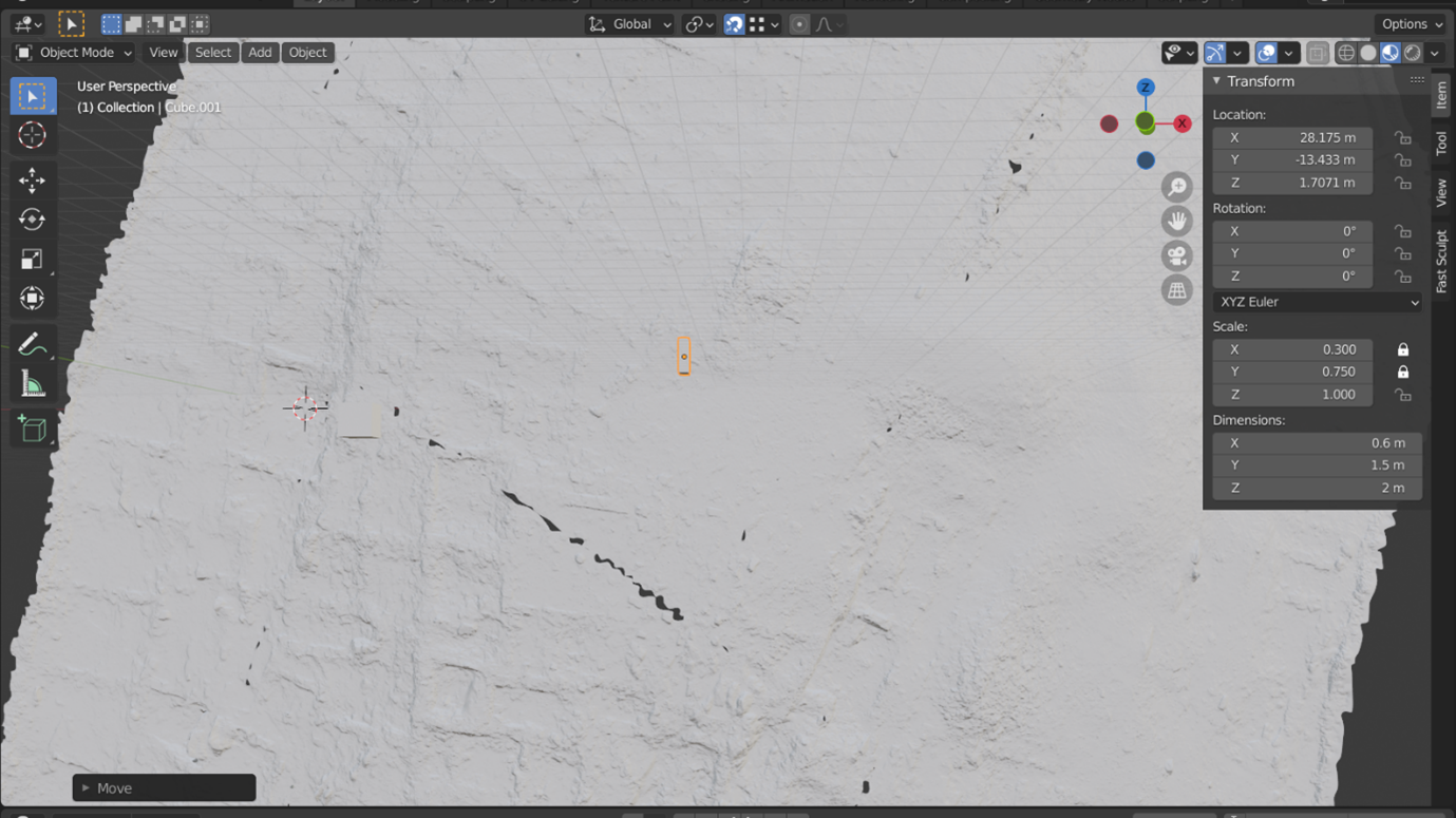
- To scale your cube to reflect these constraints, ensure that the cube is highlighted in the Scene Collection. Press the N key to call up the ‘Transform’ panel, which will appear on the right side of the 3D viewport. Keeping in mind which axis represents the ‘height’ of your scene, in the Dimensions section, change these to reflect the desired scale of your ‘walls’ in real-world units. Once these are set, in the ‘Scale’ section, enable the ‘locks’ next to the two axes you changed.
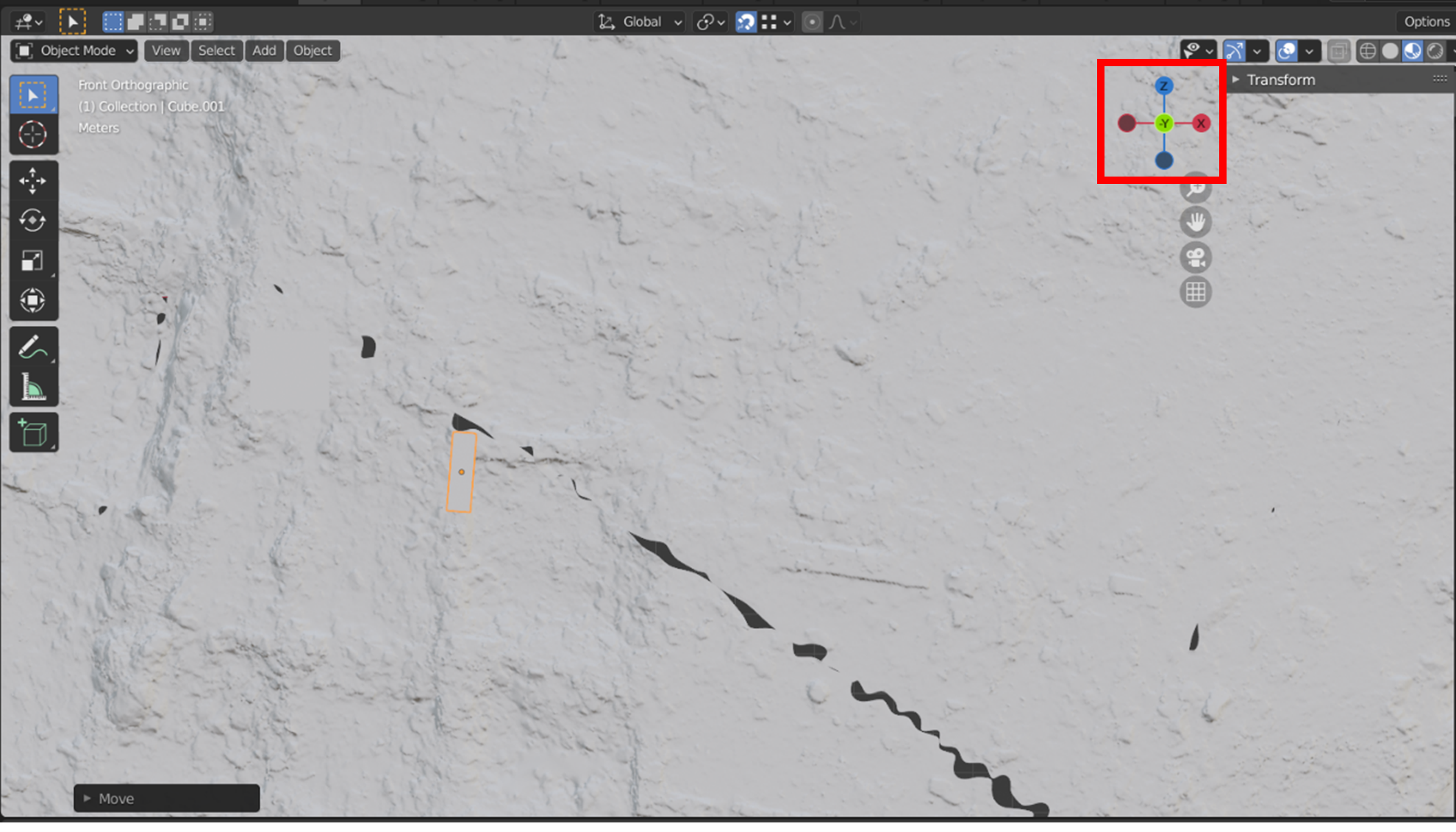
- While in Object mode, move your cube by pressing the ‘G’ kkey and align it with your starting point. If it needs to be rotated, ensure that you are looking straight down on the scene (if the Malthi data is aligned Y-up, press the green ‘-Y’ in the Navigation Gizmo (highlighted with a red box below). Then press the ‘R’ key to rotate your object until it is aligned.
- You may want to rotate the 3D space (by clicking down on your mouse wheel and moving the mouse) to check that your cube is in contact with the surface of your Malthi dataset. When ‘Snap to vertices’ is on, ensure that you hover the mouse over the bottom vertices of the cube before enabling the ‘Move’ function ( G key ), as your cube may shift below the ‘ground surface’.
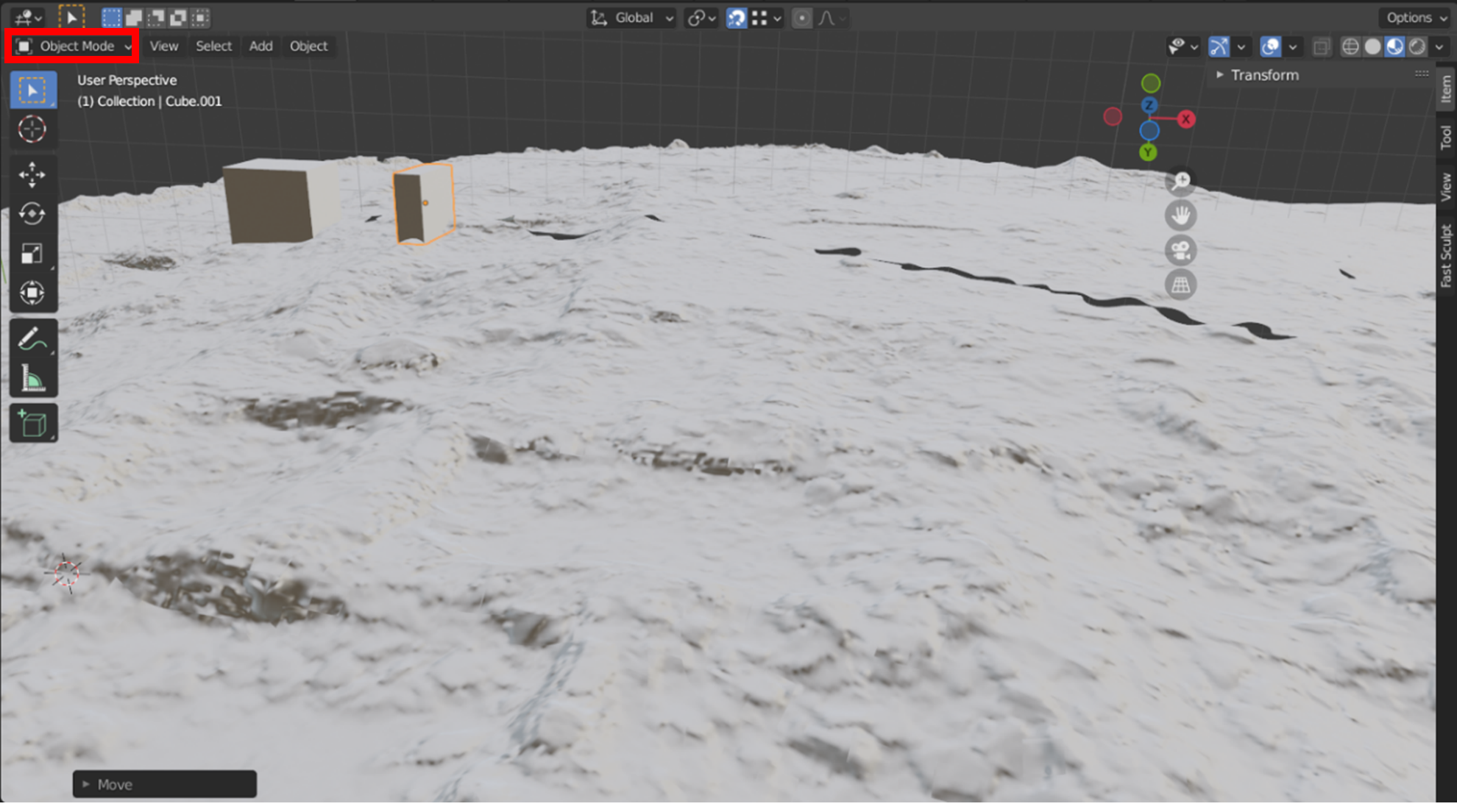
- Ensure that the cube is still highlighted in the Scene Collection and then switch from ‘Object Mode’ to ‘Edit Mode’ by pressing the Tab key , or switch it manually from the dropdown menu in the top left corner (highlighted with a red box in the image above).
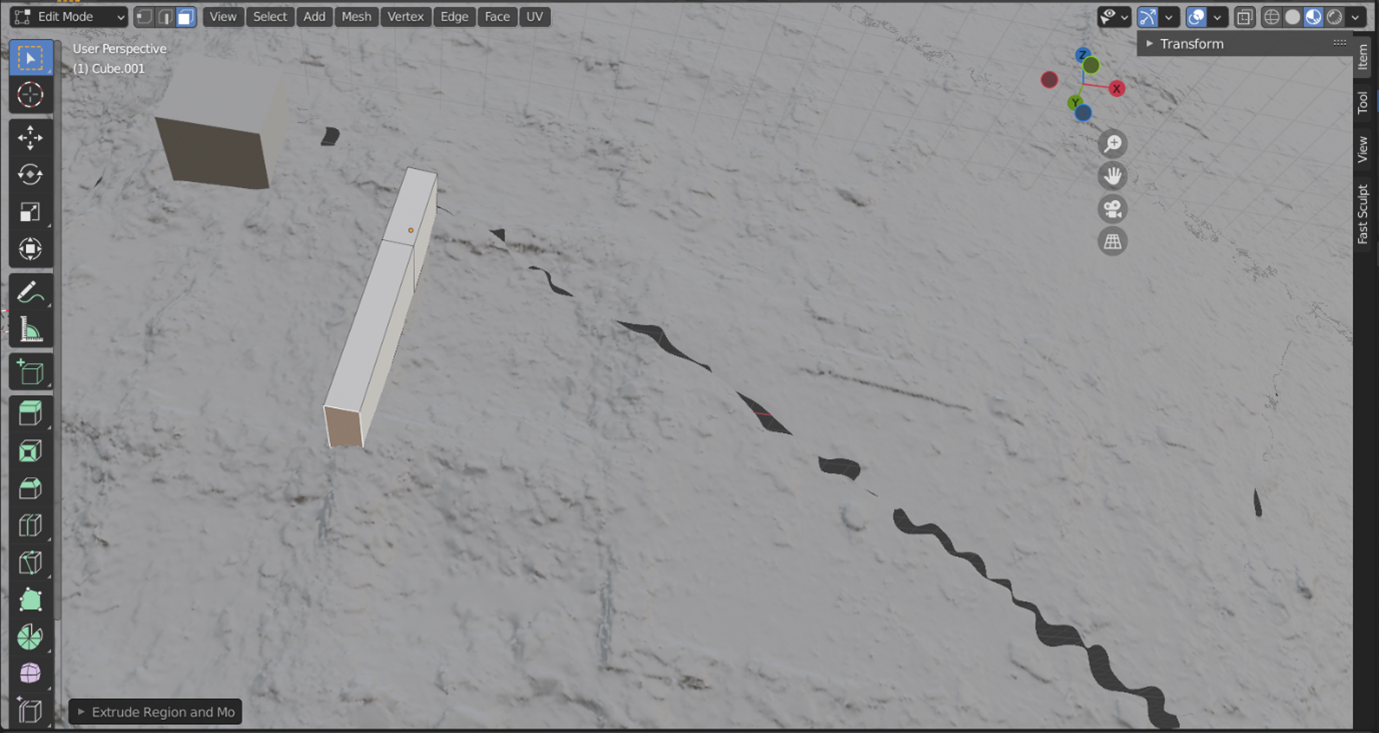
- The greyboxing process will essentially involve three processes: extruding, moving, and creating loop cuts. First, we will extrude our first cube to the next corner of our wall. Press the ‘3’ key to switch to ‘Select Faces’ mode, then select the face that will need to be pulled to the next corner.
- With that face highlighted, press the ‘E’ key to enable ‘Extrusion’. Move your mouse to the next corner and left-click when it is in position.
- If you aren’t satisfied where the cube has been placed, press the ‘G’ key to move it to a better position. Again, ensure that you are hovering your mouse over one of the bottom vertices before pressing ‘G’, or the cube may dip below the ‘ground surface’.
- • Next, we will want to create a new wall segment coming from the long interior face of our cube. To do this, we will need to create a ‘Loop cut’ by selecting the faces of our object by pressing the ‘A’ key, followed by ‘Ctrl + R’. As you hover your mouse over your cube, a yellow loop of edges will appear
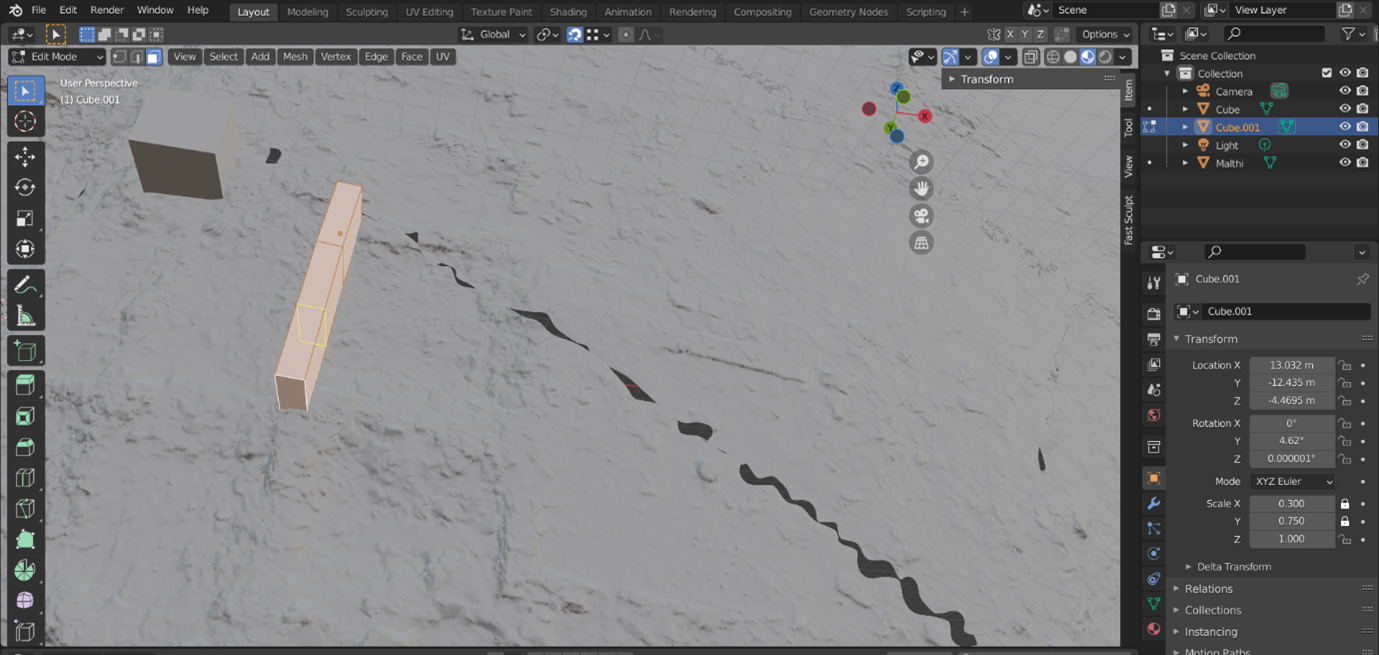
- Left-click and drag the loop – it will move along this section of your cube until you left-click again. If it is snapping to the edges of the shape too quickly, hold down the Ctrl key as you move your mouse and it will move more slowly in smaller increments.
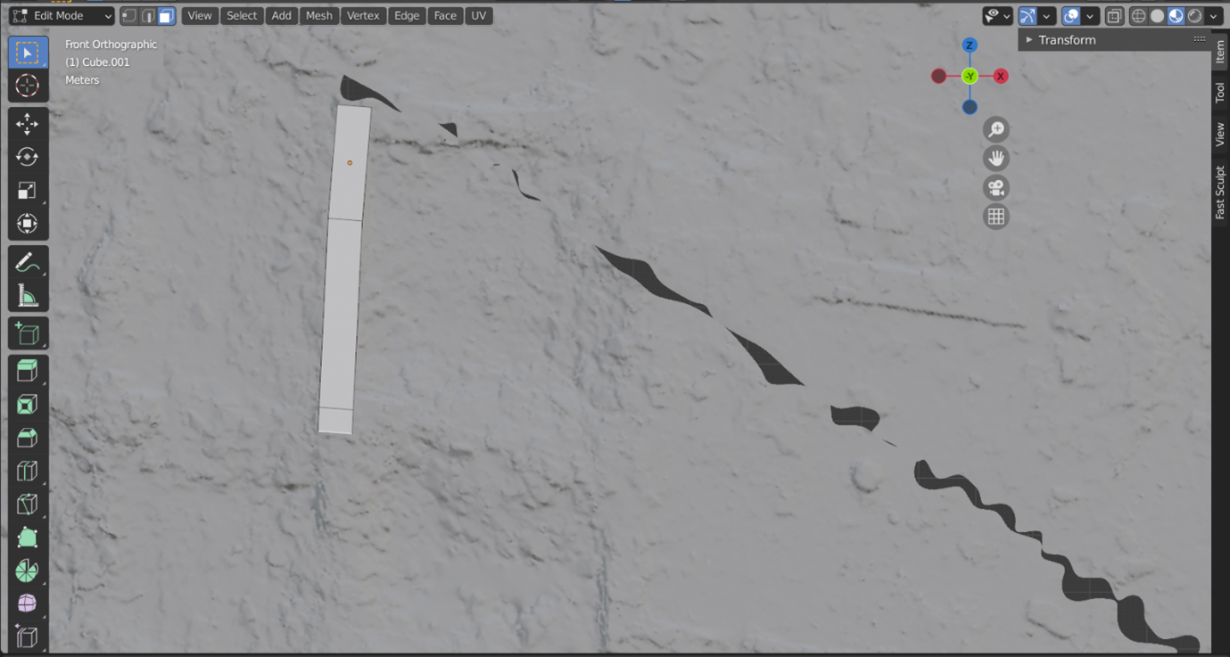
- Now we begin the cycle again; press the 3 key to switch to switch to ‘Select Faces’, select one of the faces to create an adjoining wall. Press the E key to extrude, left click when the new wall is roughly the correct length. Then press the G key to move the wall into the best position (i.e. not half-submerged as in the image below).

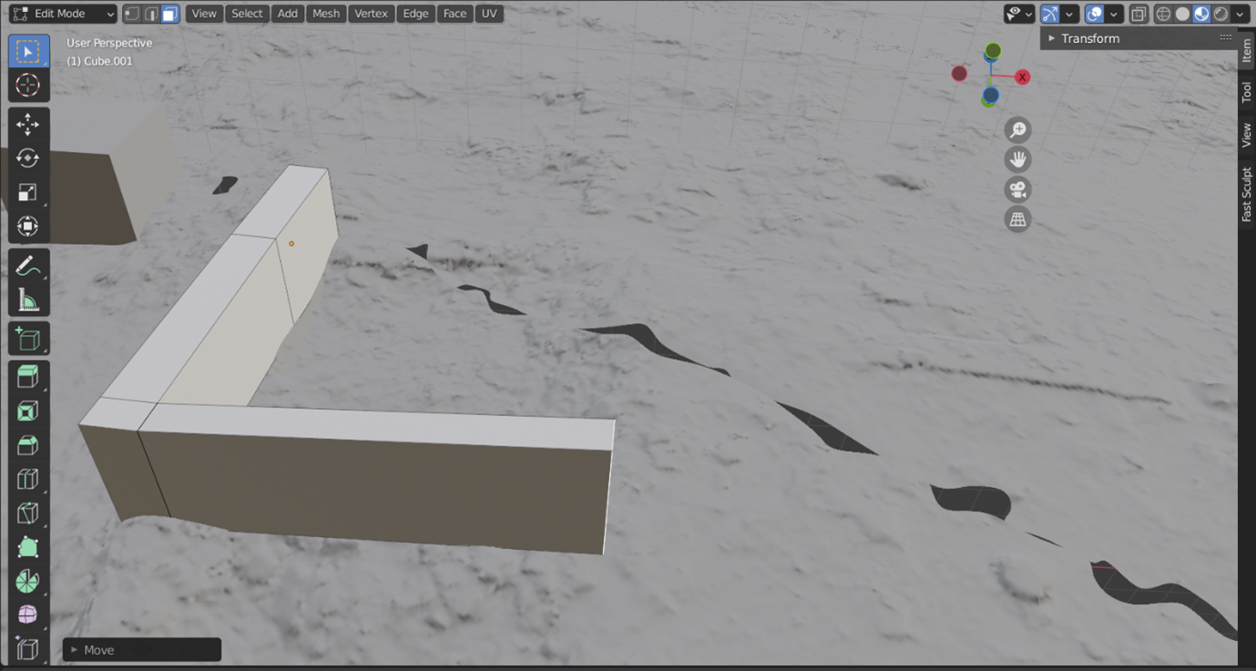
- Because these structures are not perfectly rectangular and because they were built on an uneven ground surface, at some point your extrusions will become quite distorted. When this happens, you will need to create a new cube and repeat the process. You will need to switch to Object Mode before you can create a new cube. Note that Blender will then consider these to be separate objects. It will make identifying each greyboxed area easier if you rename each object in the ‘Scene Collection’ window. Just double click on the object you want to rename in ‘Scene Collection’.
- Remember to save frequently , and that you can always use Ctrl + Z to undo an unsatisfactorily placed edge loop or a less than ideal wall placement.
Think and Respond: As you greybox your chosen area, can you identify individual rooms? Individual buildings? How certain are you in separating these? Have you been able to identify access points?
| Go back to Exercise 3 Part B | To Exercise 4 Part B |