Exercise 2
Allow at least 1 hour for Exercise 2.
Planning the next steps for Reconstructed Assets
In the first exercise, you prepared your ‘reality captured’ assets to integrate into your reconstruction. In the next steps of planning, you will need to decide how to design features that are not well preserved in the archaeological record, choose the tools you will use to design and build ‘reconstructed’ assets, and maintain a record of your modelling decisions as you make these for later archiving.
Design Decisions and Tools
Before we decide which 3D modelling software we’ll be using to create reconstructed assets, we need to identify which functions we’ll need the software to be capable of to create the reconstructed assets. There are also a series of planning/design tools which will be highlighted here, as they may be useful in the planning process, whether you are working in a team of specialists or on your own.
Note: Some of the workflow outlined here assumes that the reconstruction process is more output-focused rather than process-focused. As pointed out in Exercise 1, if your reconstruction is part of a more process-focused exercise to develop archaeological interpretations through your working process, you will need to collaborate far more often with your team and you will need to record more comprehensive paradata (particularly ‘why we didn’t go down this route’ sort of paradata) and may need to develop new methods of capturing paradata/the decision making processes.
- First, consider what you need to create for the reconstruction for this project. Think of these as ‘assets’, i.e. things that can appear, and ‘interactions’, i.e. things you can do in the reconstruction. Let’s focus on ‘assets’ first. Some common considerations in archaeological reconstructions include:
- Are you modelling the site in a potential past state or its present state?
-
Are you producing models of architecture / built environment?
- Will these be comprised of simple shapes or complex shapes? - How tall will these structures be? Will they be one level or multiple? - Will you apply colours / realistic textures?
- How will you decide what the roofs will look like?
- Will you be including the landscape context? How much of it will be visualised?
- Do we think the ground surface captured in the laser scan is essentially the same as the topography the original inhabitants built upon?
-
Will you be including people, animals, vegetation, or artefacts?
- How will you decide what these should look like? Check with your collaborators? - Will you model the interior of buildings as well as the exterior?
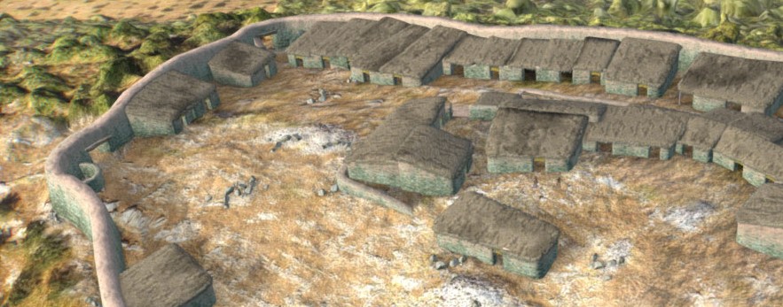
- For our specific project aim, we know we will be producing Malthi in a past state, most of what we will model will be what the built environment could have looked like, and that this will mostly comprise of complex shapes, as the foundations for the structures are already quite complex.
- We will be incorporating our ‘reality capture assets’, but we will need to create the ‘reconstructed’ assets.
When working with the archaeologists who excavated the site, you may get more direction from them on how some of the reconstructed assets should appear. It is a good idea to have a list of these questions handy prior to your first meeting with them, specifically highlighting what kind of information you need to create assets. Through excavation, there may have been materials recovered that indicate what the roofs of structures were made of (or at least how they might have appeared externally at a glance), how the walls were constructed and of what materials, and whether any buildings differed significantly in construction materials from any other structures on the site. If you are working on your own, you may have to dig through archaeological reports on the site or attempt to find comparanda from the same region and time period you are reconstructing. However, you will need to be critical of your sources – as we see by comparing the interpretations from the earliest Malthi excavations (from the 1930s) to the most recent (2015s onward), Valmin’s previous assertion that no mudbrick was used in the construction of the buildings is now contested by Worsham, Lindblom, and Zikidi (2018, 19).
To give you an idea of the sorts of questions you might want to ask your collaborators and what insights you may gain from these, I asked Dr Rebecca Worsham for her thoughts on how she would interpret or reconstruct some of the specific structural characteristics of Malthi – her answers are summarised below:
1. Which characteristics of the site do you think are particularly important to convey to a general audience and should be prioritised in the reconstruction?
Dr Worsham: While I think the accessibility/movement question is really interesting, so is the materiality/embodied experience of the site. Those are probably the easiest to interrogate with the material we have using an approach based on reconstruction.
2. Which materials seem to have been used in construction at Malthi?
Dr Worsham: The question of how high the stone foundations would have been is a good one because there is a lot of displaced rubble on the site. The stone foundations were not likely to have been much higher than 1 metre. Using mudbrick for the rest of the wall is typical of the period. We didn’t find much at the site, but with Valmin’s excavation and the fairly shallow stratigraphy, there probably wasn’t much left to find. Wood supports are also fairly typical, sometimes embedded within the walls, but we saw no evidence of that. For the roofs, we don’t believe they were tiled. Tiled roofs weren’t unknown, but Valmin didn’t find many tiles, and the ones he did find are likely to be later and/or fragments of storage vessels. We were going to reexamine them, but we think they were lost in an earthquake. So our best guess is that the Malthi structures probably had wooden/thatched/mudded roofs. All of the structures are highly uniform in the remaining materials. Basically everything looks the same, both in the materials and in the actual construction.
On the towers, there really isn’t much visible of the fortification wall today, so Valmin could have found something like a tower. There are earlier examples (Early Bronze Age), here for example. There are also later Mycenaean bastions at the palace sites (like Mycenae). There might be a contemporary example at Kolonna on Aegina, but I would have to check the dates on the various phases of their enormous fortification wall.
3. Would most of these structures have been single story structures, or two? How tall would you think the buildings would be?
Dr Worsham: I suspect several of the buildings, at least toward the central area of the site and along the change in slope there, would have had two storeys. I haven’t thought about how tall they would be yet, but the lower floor for one of them must have been at least 1.3-1.5m, I suspect. If that was a basement, then the upper floor could have had higher ceilings. They may also have been using the roof space as an additional work/sleeping area, depending on the roofs. But that would help deal with the real crowding on the west side of the site, for instance.
4. If the fortification wall is usually between 2m and 3m thick, what would you estimate as the original height of the wall?
Dr Worsham: We aren’t sure about the original height of the fortification; we have had a lot of debates. Michael restored it to be fairly high at about 4 metres. I’m not sure that it’s entirely clear that the fortification wasn’t chiefly a retaining wall to create the building surface inside. There are a lot of unaccounted for stones, and the earlier fortifications had mudbrick on top of the stone foundations. I would think the fortification would not be much higher than the houses that line it. This is all guessing!
5. How closely do you think the ground surface recorded in the 2015 laser scan resembles that of the ground surface during the site’s occupation?
Dr Worsham: There isn’t much ground cover on the site, but it seems like they liked making use of the bedrock for quarries and building surfaces. There are enough fairly clear pathways that at least it seems in some areas to be fairly close to the original ground level. But it’s also fairly clear that some material eroded down the hill and built up against the fortification wall. Valmin also removed a fair amount of soil (though he also seems to have backfilled some areas), but his sections look deeper than what we found. So there may be more soil in the laser scan than the original ground level, but it’s probably still fairly close.
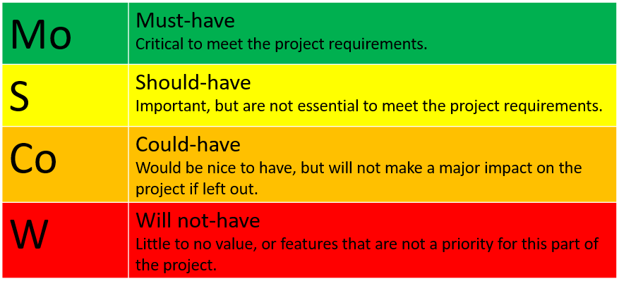
MoSCoW Method
Let’s now consider briefly what type of interactions we could incorporate into the reconstruction, as this is important to think about the possibilities during this stage, though these will be considered more extensively in Exercise 5 when discussing the platforms through which the final output could be made available. The simplest interactions you may want to incorporate would be allowing users to ‘walk through’ the site, either by teleporting to predetermined hotspots or by allowing the user to ‘walk’ as one would in most video games. You could create localised annotations that users can click on to receive more information about a feature. More complicated interactions might involve allowing a user to ‘pick up’ an object and observe it more closely. You may even wish to enable VR or AR application use of the reconstruction.
When considering the different possibilities for your reconstruction, whether creating ‘assets’ or possibilities for ‘interaction’, it is often useful to create a ‘wish list’ of sorts for the assets or functionality to be incorporated into the final reconstruction. You can then apply the MoSCoW method, the invention of which often attributed to Dai Clegg and Richard Barker (1994) to guide software development, which helps to prioritise features according to how essential they are to meet the project aims. The list can be classified into ‘Must haves’, ‘Should haves’, ‘Could haves’, and ‘Won’t haves’. Not only will this help you, as the reconstruction artist, prioritise what tasks should be completed first for time management purposes, but it will also manage the expectations of the rest of the team. If the team decides that reconstructions of artefacts are only ‘Could haves’, no one will be surprised that reconstructed pottery does not make an appearance in a reconstruction designed to understand how one might have navigated the site. Walls scaled to appear at least 2 metres in height in the reconstruction, however, would likely be considered a ’Must have’ so that one could understand how the presence of buildings affected visibility in certain parts of Bronze Age Malthi.
Try it yourself! Create a list of potential features and interactions you could include in a reconstruction of Malthi. Assign each of these according to the MoSCoW method – think about how you decided which features were ‘must haves’ rather than ‘should haves’. Which factors could change how you’ve classified these? If more time was available for the project? Add these to your Design Document, which you started in Exercise 1.
As you make these design decisions, it is important to keep track of your reasoning behind making these decisions. While paradata will be discussed again in the additional archive materials, in general most will agree that in your paradata you should include 1) the sources, references, and data utilised in the reconstruction, 2) a summary of the changes made to ‘real’ datasets captured via 3D recording methods (if incorporated), and 3) a summary of the choices/justifications/assumptions made in representing uncertain elements of the reconstruction.
One of the most common ways to ensure a good level of paradata is recorded is to keep some sort of diary, much like the blog produced by Kastanis (2019). This should include:
- A specific list of the resources and comparanda utilised;
- A summary of the different choices made accompanied with a short justification;
- A reference for the original datasets utilised in the reconstruction (if any); and
- A record of the decisions made when discussing the project with other members; this may include saving emails and notes to refer back to at the end of the project.
There are a variety of other methods and design tools that you may need at your disposal, particularly if you are collaborating at some distance from the other members of your time. You may want to create sketches of what you think the ‘reconstructed’ assets should look like (perhaps to share with your collaborators, to get their input). While pen and paper are classic materials to use in this process, with the increasing emphasis on online working and collaboration, you may wish to use an on-screen sketching or storyboarding software. Free and open source, Storyboarder is an option, though there are many others that have free trials available.
There is another method which you will likely use, called greyboxing. A term often used by 3D environment artists or game level designers, this uses simple shapes, like cubes, to lay out the basic shapes of your environment to get a sense of scale and flow of movement through a space. If things change, you can do this flexibly without removing assets that have taken substantial work. This process could also be used to test lighting and other effects. We will employ this method in Exercise 4.
Which software tools are suitable for creating our reconstructed assets?
You now have some familiarity with CloudCompare, but you will need different tools for the next step of the process, because the tasks will be different. There are many 3D modelling packages available on the market, but you need to be able to critically assess which are best suited to your project. There are a number of factors that you need to take into consideration, including but not limited to:
- Cost – how expensive is the software? Does it have a student license available, and how long are you able to access it for? Do you need to purchase it for future freelance projects, or do you aim to work for a place that will provide it for you? Will your machine be able to handle the software required, or will you need to invest in a new computer? Any accessories?
- Functions available – what sort of modelling functions will you need for the project? Is the software better suited to modelling modern architectural shapes or organic shapes? Both? Will you need to invest in additional specialised software to add specific functionality (i.e. sculpting, animating, etc)?
- Complexity – is the User Interface intuitive or difficult to follow? Is the software specialising in one specific function, or does it combine multiple functions in a single package? Does it do this well?
- Investment in skills development – how long has the software been available? Will it still be around in five years? Is there a large community using the software? Is this considered an ‘industry standard’? Are there up-to-date tutorials available online?
To address these questions fully, we will take a few different approaches; we will take a brief look at the history behind the software’s development, search the software’s documentation for key words, and look at completed projects that utilised the software. We’ll be looking at the most commonly used 3D modelling software packages, including Autodesk 3DS Max, Autodesk Maya, Blender, Zbrush, and Cinema4D (not BIM or CAD software like Revit or Sketchup.)
Autodesk 3DS Max – Like many 3D modelling software, Autodesk 3DS Max derived from an early 1990s software that is considered one of the industry standards in 3D modelling. Assets created in 3DS Max have featured in video games, TV/films, and architectural rendering. At a basic level, 3DS Max is better at creating modern architectural shapes rather than organic shapes, but this is largely due to how Autodesk’s products have developed over time. They are specialist software designed to do one category of tasks well; another type of Autodesk software will excel in a different set of tasks. For example, if we are concerned about how well-suited the software is to creating organic shapes, we can navigate to Autodesk 3DS Max’s product documentation and search for the word ‘sculpt’; most of the entries suggest that Autodesk Mudbox will be better suited to the task. If we had wanted to keep the laser scan data in point cloud format, we could search for ‘point cloud’ to see how well 3DS Max works with point cloud data. It does appear that point clouds can be imported into 3DS Max, however the documentation suggests that it must be in an Autodesk ReCap file format (.rcs or .rcp). So while the Autodesk suite of products is often considered the ‘industry standard’ of the 3D modelling community, it is better to employ these if you have access to as many as you will need and have the hardware to support them. In terms of learning and tutorials, however, Autodesk clearly invests a great deal in creating tutorials, as each software package has its own YouTube channel. Their website highlights an archaeological example of a digital reconstruction, the Tomb of Nerfertari, which is also viewable on Sketchfab.
Autodesk Maya – As a part of the Autodesk collection of software, Maya is software designed for creating characters, scenes, and animating realistic effects for video games, animated films, and TV. It was developed in the late 1990s and was finally purchased by Autodesk in 2005. Because the software was designed for arts and entertainment purposes, it contains a wider range of artistic tools, including sculpting. If we search the documentation for ‘sculpt’, we are presented with many more options. The documentation does suggest, however, that it works best with a graphics tablet, which you may not have access to. Unsurprisingly, if we search for ‘point cloud’, however, it appears that these are most often used for particle effects in Maya. There are a few entries that suggest that it could be possible to use point clouds as geometry, but a perusal of online fora suggest this is not common practice. Like 3DS Max, Maya has its own YouTube channel with a series of tutorials available.
Blender – Blender is best known as the free open source software for 3D modelling, UV unwrapping, texturing, animating in both 2D and 3D, and graphics. It, like 3DS Max, was original developed in the early 1990s, though its first truly open source stable release was in 2003. Though it had originally been notorious for its less standardised UI, this has been greatly improved with the 2.8 release. In terms of software requirements, Blender is much more accessible; they advertise that Blender can be run from a USB stick and is fully portable. When searching Blender’s documentation for ‘sculpt’, it is clear that it has a specialised sculpting mode, much like Maya and Zbrush, so we will be able to use this to create our more organically shaped prehistoric dwellings and materials. If we search for ‘point cloud’, the documentation clearly states that there is not much that can be done with point clouds in Blender yet, apart from particle effects. Like the Autodesk and Zbrush software, Blender provides tutorials on their YouTube channel. The primary drawback to Blender is that it is such a jack-of-all trades software, that more specialised software will likely have more options and flexibility in their expertise. There is also less direct support/interactivity between other software packages, like Autodesk, though the broad range of Blender’s inbuilt functions makes this less of an issue. Blender is used by some archaeological reconstruction specialists, including Bob Marshall and AnthroYeti (aka Edward González-Tennant).
Zbrush – Pixologic’s Zbrush is a specialised 3D sculpting software that was developed in the mid-2000’s and released in 2007. Like Maya, its workflow is more like sculpting for more organic modelling. It is often used for creature creation and medical animation and is able to ‘bake’ high resolution detail into decimated versions of the 3D model. It supports integration with other software, including Autodesk 3DS Max, Maya, and Cinema 4D, so much so that Autodesk has integrated Zbrush into some of its Maya tutorials. Its complex decimation functions may be part of the reason it has been visibly integrated into Autodesk’s workflow. If we search for ‘decimation’ in Zbrush’s documentation, we find a number of features including the ‘Decimation Master’ function. In contrast, if we search for ‘decimate’ in Maya’s documentation, it instead returns with searches for ‘decimal’, and searches for ‘decimation’ return with no results (though it does appear in 3DS Max’s documentation). Zbrush’s mesh focus is clear, however, as searching for ‘point cloud’ in its documentation returns with no results. One of the main drawbacks to Zbrush is that it takes up a great deal of space on the computer’s hard drive, as do its ‘temporary save’ files. Zbrush has been used in archaeological reconstructions of a different kind – in the facial reconstruction of a mummy.
Cinema 4D – Maxon’s Cinema 4D is focused on all of the 3D modelling, animating, rendering, and texturing necessary to produce a 3D animation. There are sculpting tools in the software, as a search for ‘sculpt’ in Cinema 3D’s documentation provides many results. Like many of the other software packages discussed here, a search for ‘point cloud’ results in only particle effects. Cinema 4D also provides a variety of guidance on Maxon’s YouTube channel. Like the other industry standard software packages, Cinema 4D has a great deal of external support/compatibility, including with After Effects, Adobe Illustrator, Unreal and Unity.
To directly compare the system requirements for each of these in a tabulated form, see the Software Comparison table.
Think and Respond: Given your searches through the software documentation and the Software Comparison table, which options would be best suited to this project? Which options are best suited to your budget/future skills building?
For this exercise, we will be utilising Blender due to its open access approach and its recently improved UI. While not the ‘industry standard’, it is flexible and self-contained and, for the ambitious student, has the option to code/adapt as needed. It is surrounded by a large community and, in addition to the official tutorials, there are a number of user-created tutorials available online.
Resources for Exercise 2:
- Clegg, Dai; Barker, Richard (1994). Case Method Fast-Track: A RAD Approach. Addison-Wesley. ISBN 978-0-201-62432-8.
- Frankland, T. 2012. A CG Artist’s Impression: Depicting Virtual Reconstruction Using Non-photorealistic Rendering techniques. In (eds) Chrysanthi, A., Murrieta Flores, P., and Papadopoulos, C. Thinking Beyond the Tool: Archaeological computing in the interpretive process. Oxford: Archaeopress. Pages 24-39.
- Lindblom, M., and R. Worsham. Forthcoming. “Visualizing the Past: A 3D Reconstruction of Early Mycenaean Malthi in Messenia.” In Power and Place in the Prehistoric Aegean and Beyond, edited by S. Allen, M. Lee, R. Schon, and R. A. K. Smith, INSTAP Academic Press.
- Kastanis, L. 2019. Authenticity in Digital Archaeological Reconstructions: A Workflow Pipeline and Data Classification System to Inform and Validate the Digital Reocnstruction Process. Unpublished thesis. Queensland University of Technology. https://eprints.qut.edu.au/132652/.
- Sullivan, E., Nieves, A. D., and Synder, L. M. 2017. Making the Model: Scholarship and Rhetoric in 3-D Historical Reconstructions. In (ed) Sayers, J. Making Things and Drawing Boundaries: Experiments in the Digital Humanities. Minneapolis: University of Minnesota Press. Accessed from: https://dhdebates.gc.cuny.edu/read/untitled-aa1769f2-6c55-485a-81af-ea82cce86966/section/d441edf8-4e56-4721-a3f4-0a9a1674c15f#ch35.
- Worsham, R., Lindblom, M., and Zikidi, C. 2018. Preliminary report of the Malthi Archaeological Project, 2015–2016. Opuscula, 11: 7-28.
- Yang, R. 2017. How To Graybox/Blockout a 3D Video Game Level. Blog. URL: https://www.blog.radiator.debacle.us/2017/09/how-to-graybox-blockout-3d-video-game.html.
| Back to Exercise 1 Part C | Continue To Exercise 3 |