Exercise 2: Taking measurements in MeshLab
(Allow at least 20 minutes for Exercise 2)
A step-by-step video guide to Exercise 2 can be found here.
Visually inspecting 3D models is necessary to familiarise yourself with the dataset, to make initial judgements on the suitability of reused data for your research, and to take note of your initial observations, like patterns of similarities and differences in appearance. But to investigate questions like whether the same individual created two different pots, whether the distance between a series of fingerprints suggests that they all belong to the same hand, or whether different fingerprints were made during different stages of the manufacturing process, we need to be able to take measurements to assess the size and distance of these features more rigorously. In this exercise, you will learn to:
- Carry out simple measurements from 3D models in MeshLab.
Recall that models need to be scaled for us to be able to take measurements from them or use them in quantitative analyses. While the scale of the object does not matter so much in visual assessments, it is necessary in metric assessments. Without scale, the Colosseum and a soup bowl are about the same size in 3D. It should be stated somewhere in the metadata of the dataset how the 3D models have been scaled; in this case, the Boston Fingerprints dataset has been scaled in millimetres.
Why is scaled data necessary for measurements? While 3D models can be accurate visual representations of real-world objects, the 3D model needs to be scaled for metric analysis to be meaningful. If the 3D model is scaled, the measurements taken from the 3D model correspond to real-world measurements of the original, physical object (in real-world units, often millimetres or metres). Without being scaled, the units of the 3D mesh in the software are completely arbitrary and will not correspond to the actual dimensions of the real-life object.
The Measuring Tool
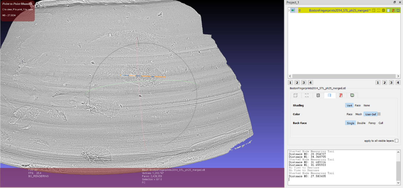
If you want to measure between two points on the 3D model, you can use Meshlab’s measuring tool (which looks like a measuring tape on the toolbar, highlighted with a blue box below). Click the icon, then left-click the two points on the 3D model you want to measure between. An orange line should appear between the two points, and you will be able to move the 3D model around to ensure the accuracy of the measurement. If you click on the measuring tape again, you can continue to create new measurements. When you double-click on the measuring tape icon, the orange lines will all disappear, though your measurements will still be recorded in the window in the bottom right corner.

Try it yourself!
- For this exercise, open the STL file for PH_25. Begin by measuring the lengths of the fingerprints you can identify on PH_25. Examine your own fingers – Are your fingerprints longer, or about the same? If the fingerprints on PH_25 all belong to the same potter, can you guess at which finger(s) the prints might belong to? Take a screenshot of your measurements to add to your gallery.
- Try measuring the distances between the fingerprints you see – is it reasonable to suggest these are from the same hand and the same fingerprinting ‘event’? Why or why not?
- Are there any fingerprints that are unlikely to belong to the same hand/fingerprinting ‘event’? Why is this?
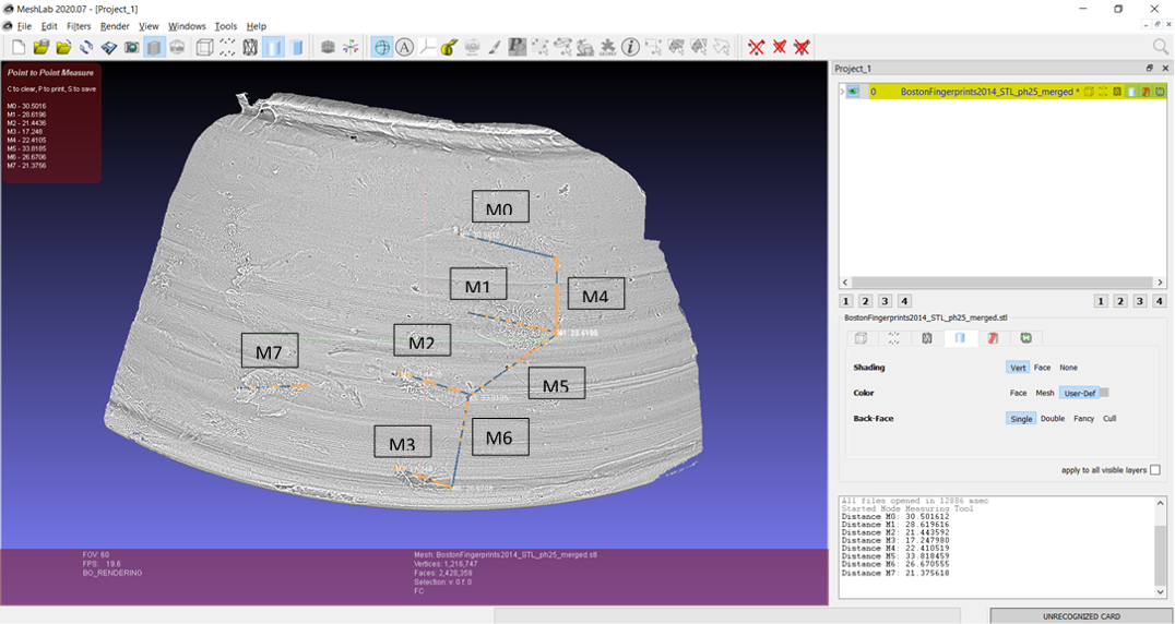
One could interpret that the fingerprints M0, M1, M2 and M3 are from the same hand and the same ‘event’ of the potter touching the pot, but would the arrangement of these prints allow M7 to represent the thumb print from the same ‘event’? Try arranging your fingers to match this layout – it is difficult, though the shape of the bowl might have influenced their placement. There is also the possibility that M3 was not made during the same ‘event’, as it is not clear whether the print ridges are curving in the same direction as M0, M1 and M2.
Reflect and Write
- Looking at your screenshot, how would you interpret the fingerprints on PH 25?
- What stage of the manufacturing process might these represent? What has led you to this conclusion?
- Write a short caption explaining your reasoning to accompany your screenshot in your gallery.
Meshlab is powerful software; in this tutorial, we have only scratched the surface of how it can be used to visualise 3D data. However, the vast majority of Meshlab’s functions are not intuitive. Fortunately, there are many tutorials available online, the most popular of which is the YouTube channel Mister P. Meshlab Tutorials.
A step-by-step video guide to Exercise 2 can be found here.
| Back to Exercise 1 | To Exercise 3: The Basics of CloudCompare |