Exercise 1: Familiarising Yourself with 3D Data in MeshLab
(Allow at least 30 minutes for Exercise 1)
A step-by-step video guide to Exercise 1 can be found here.
The purpose of this initial exercise is to:
-
Become familiar with the Boston Fingerprint project dataset;
-
Learn how to orient, navigate and visualise 3D models in Meshlab;
-
Identify common errors in 3D data caused by data capture methodologies or the materiality of the recorded object.
When reusing a dataset, it is important to first explore and inspect the data to ensure that it is suitable for your research. It is often difficult to orient a 3D model, particularly when you have not seen the recorded object in person, because you are viewing 3D data on a two-dimensional screen. It is also important to be familiar with common errors and their causes, especially when working with reused data, because they affect the quality of the data and your interpretations. In this exercise, we will be orienting the 3D data to match the alignment of the reference photograph included in the dataset. This exercise will also introduce some simple and useful visualisation tools that will allow you to quickly judge the suitability of the dataset to address your research question (i.e. are the fingerprints clear enough in the dataset to identify similarities; are specific ceramic manufacturing techniques identifiable?).
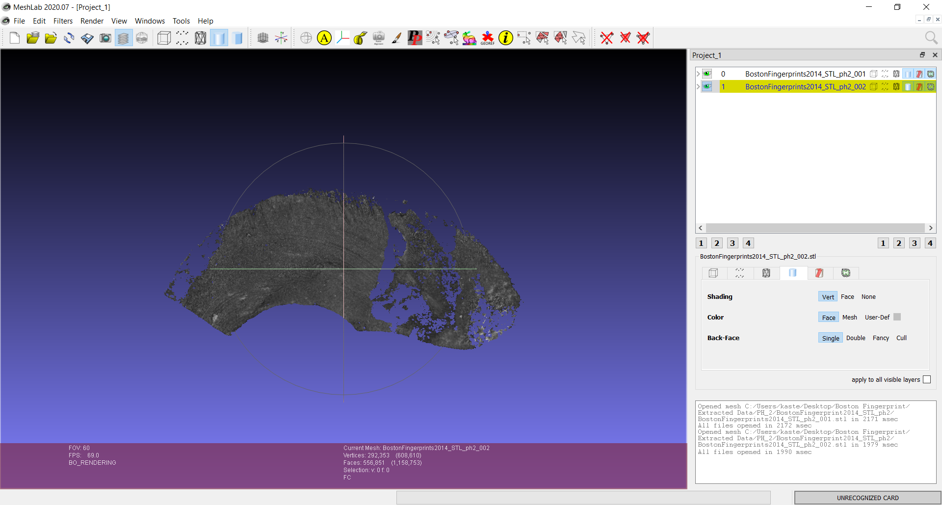
- First, open MeshLab. Import the STL files for PH_2 – you can either do this by selecting ‘Import Mesh’ from the File dropdown menu, the icon for ‘Import Mesh’ on the toolbar, or by hitting Ctrl+I. Import both BostonFingerprints2014_STL_ph2_001 and 002. Your screen should look like this.
-
On the left, you can view the 3D model. Note the two lines and circle surrounding the sherd – this is called the trackball and allows you to move the 3D model in any direction. On the top-right of the screen, you can see that both files are in the project. Click the ‘eye’ symbol next to each file; this will turn the visibility of the 3D data on or off. When a file name is highlighted in yellow, this means changes will be made to this mesh only.
-
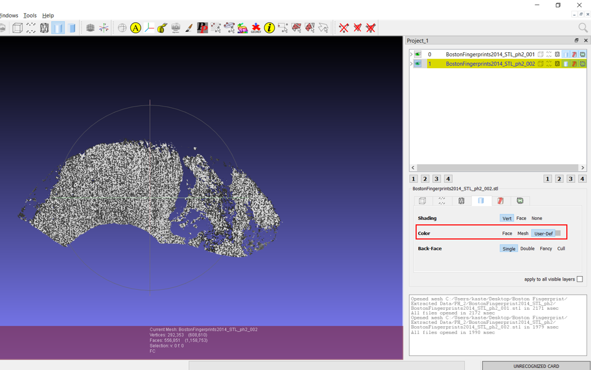
To turn off the colour of the 3D models, select the file name, and switch the Color setting from ‘Face’ to ‘User-Def’. Repeat this step for the second STL file.
- To accentuate the topography of the 3D model, Shaders can be applied. MeshLab provides a variety of options for these under the ‘Render’ dropdown menu. One that is particularly useful here is the ‘Radiance Scaling’ shader. A menu should pop up – to increase the contrast between the features, click and drag the sliding scale to the right (highlighted below).
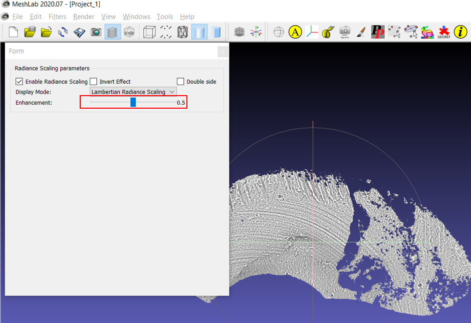
What is a Shader? Shaders are powerful visualisation tools. They render the appearance of the surface based on a number of factors, including lighting position and >transparency, view position, material properties, and shape of the 3D surface. Complicated algorithms underly these shaders – take a look at this publication on Meshlab’s >Radiance Scaling algorithm to get a sense of the complexity!
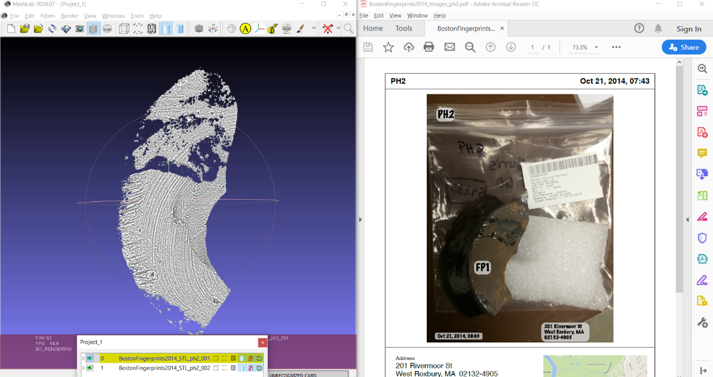
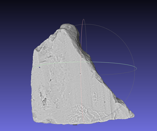
- Open the Reference Image for PH_2. In the photograph, you can see that the location of fingerprints identified by researchers have been marked with labels. To find this fingerprint, orient the 3D model to the position of the sherd in the photograph. Left-clicking and dragging in a direction anywhere in MeshLab’s 3D space will turn the 3D model around, but if you use the trackball (the circles surrounding the 3D model), you will have better control over how the 3D model moves. If you have a mouse-wheel, you can use this to zoom in and out of the 3D model. Clicking down on the mouse-wheel will pan the 3D model in any direction. Your 3D model should end up looking like this.
Potential Data Capture Issues
Notice that there are significant gaps in the data which look like holes in the 3D model. If we examine the reference image, these holes correspond with areas on the potsherd that are treated with a black glaze. Black and shiny surfaces are often difficult to capture using any digital imaging approaches, including structured light scanning (the method used to capture this dataset); these areas were not recorded by the software and now appear as holes in the 3D model.
However, the rest of the ceramic is recorded quite well – if you examine the area to the right of the FP1 label, but on the 3D model, you should see a partial fingerprint preserved in the potsherd.

In addition to recording errors caused by the properties of the object (like the black, reflective glaze above), there are errors that can be caused by the recording process itself. Restart MeshLab and import the STL files for PH_4 into a new project. Change the ‘color’ of the STLs to User-Defined, and then apply the Radiance Scaling shader. You may notice that some strange light-grey diagonal striations on the potsherd.
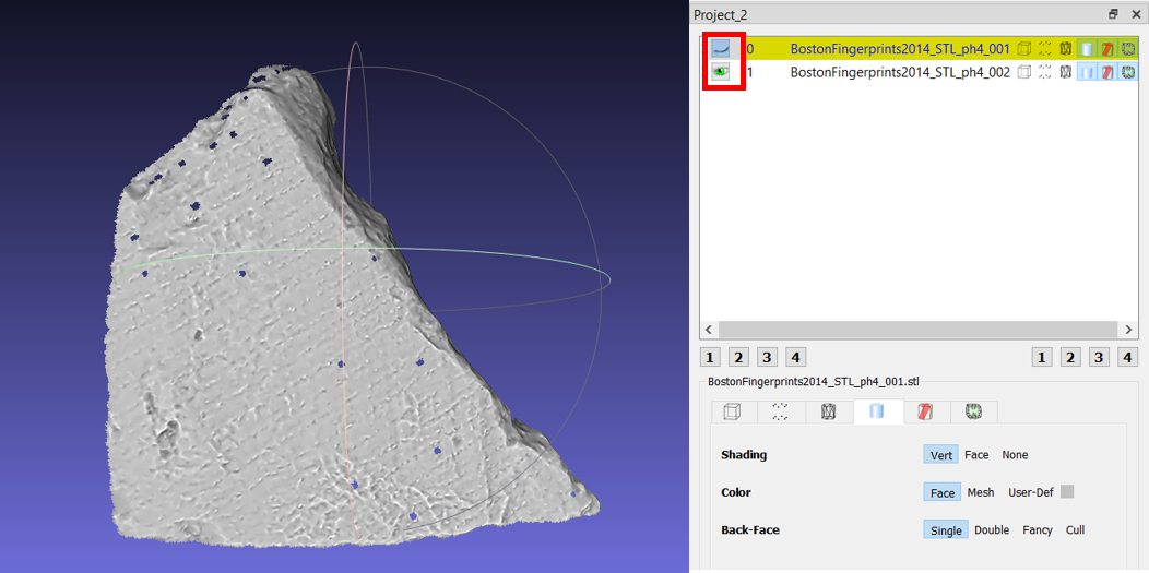
If we turn off the visibility of STL_ph4_001 (by clicking the eye symbol next to the layer, highlighted in the red box below), we find that the data for STL_ph4_002 is ‘stripey’. This seems to occur when the object is slightly out of the field-of-view of a structured light scanner, or the scanner was not pointing exactly straight-on at the surface of the potsherd at the time of recording (perpendicular to the recorded surface). Because ceramic vessels are not usually flat surfaces, this does occur from time to time, but it does not usually affect the legibility of the data. It is important to be aware of it, however, so that the error is not interpreted as something culturally significant.
Try it yourself! Try these steps with at least another three potsherds from the Boston Fingerprints datasets – can you orient the 3D models to match the reference image and find the fingerprints on the 3D models? Assess whether these fingerprints are defined enough to identify ridge patterns.
Reflect and Write
- What else can you tell about the pottery from looking at these 3D models? What stages of the manufacturing processes can you identify? Were the surfaces of the potsherds all >treated in the same way? Take notes on the differences in appearance between the sherds – are these signs for different manufacturing processes? Do you think these were choices >made by the individual potter, or do these hint at different vessel types with different uses?
- Try different shaders – are there any that define these details further? Take a screenshot of a potsherd with a different shader applied; write a long caption for the image >reflecting on how well this visualisation informs you about the artefact itself.
A step-by-step video guide to Exercise 1 can be found here.
| Back to the Introduction | To Exercise 2: Taking measurements in MeshLab |